Review
. 2018 Feb 26;8(1):17.
doi: 10.3390/bios8010017.

Simple Approaches to Minimally-Instrumented, Microfluidic-Based Point-of-Care Nucleic Acid Amplification Tests

Affiliations
Review

Simple Approaches to Minimally-Instrumented, Microfluidic-Based Point-of-Care Nucleic Acid Amplification Tests

Michael G Mauk et al. Biosensors (Basel). .

Abstract

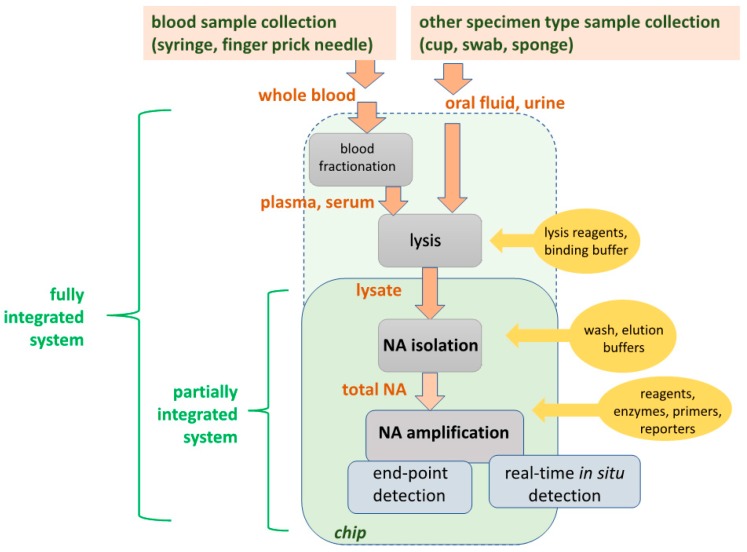
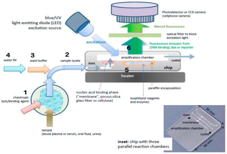
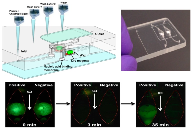
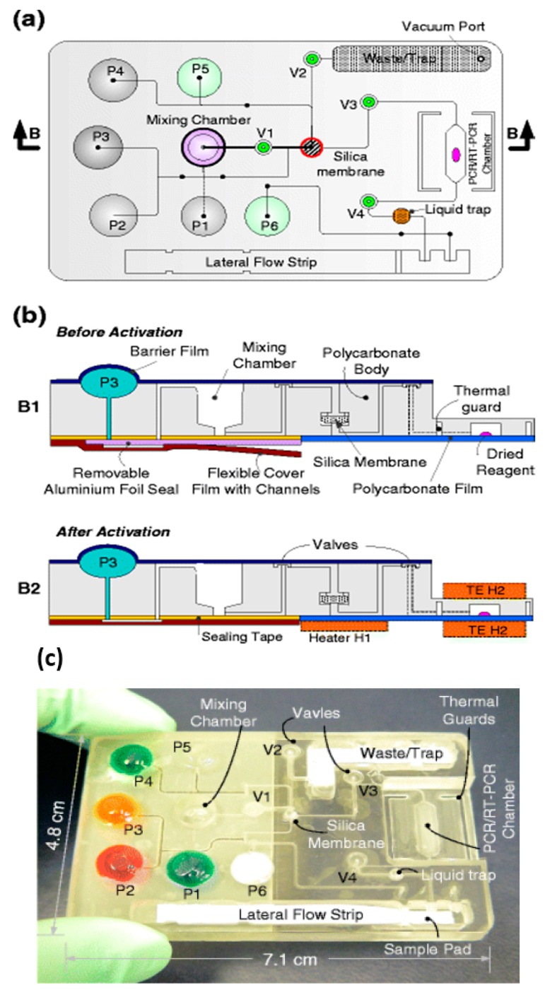
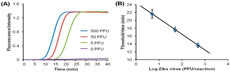
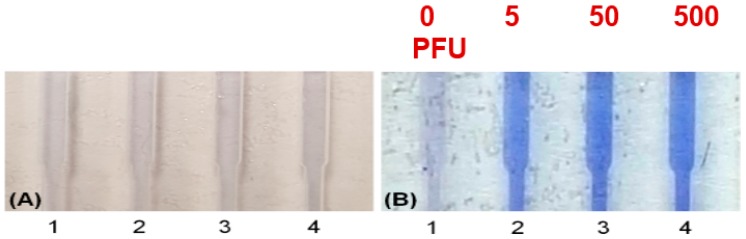
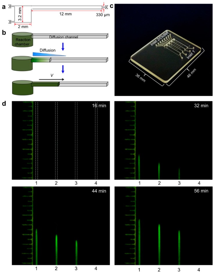
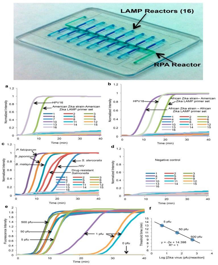
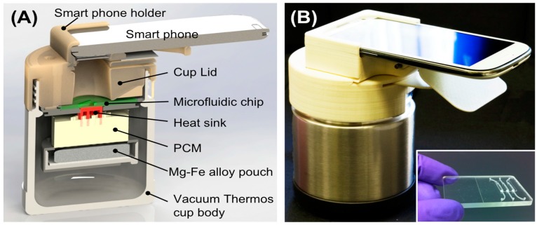
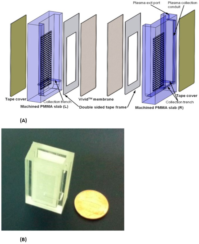
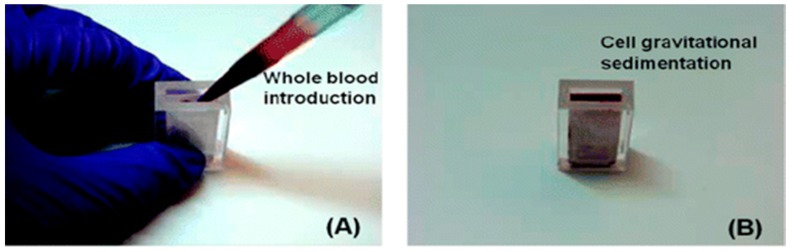
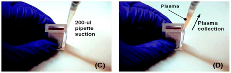
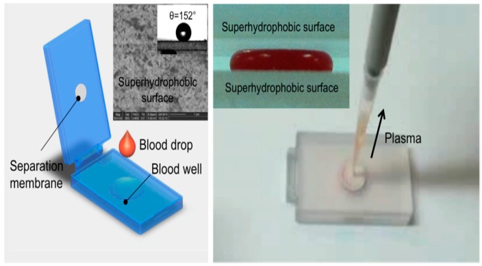
Designs and applications of microfluidics-based devices for molecular diagnostics (Nucleic Acid Amplification Tests, NAATs) in infectious disease testing are reviewed, with emphasis on minimally instrumented, point-of-care (POC) tests for resource-limited settings. Microfluidic cartridges ('chips') that combine solid-phase nucleic acid extraction; isothermal enzymatic nucleic acid amplification; pre-stored, paraffin-encapsulated lyophilized reagents; and real-time or endpoint optical detection are described. These chips can be used with a companion module for separating plasma from blood through a combined sedimentation-filtration effect. Three reporter types: Fluorescence, colorimetric dyes, and bioluminescence; and a new paradigm for end-point detection based on a diffusion-reaction column are compared. Multiplexing (parallel amplification and detection of multiple targets) is demonstrated. Low-cost detection and added functionality (data analysis, control, communication) can be realized using a cellphone platform with the chip. Some related and similar-purposed approaches by others are surveyed.

Keywords: LAMP (loop mediated amplification); NAAT; RPA; lab on a chip; microfluidics; molecular diagnostics; nucleic acid amplification test.


Conflict of interest statement

The authors declare no conflict of interest.

Figures

Figure 1
Figure 1
Processing steps (‘unit operations’) of Nucleic Acid Amplification Tests (NAATs) molecular diagnostics. Plasma from whole blood samples, or raw oral fluid or urine, is lysed to release nucleic acids (DNA or RNA) from virus or cellular pathogens. The soluble nucleic acid is isolated in a purified, concentrated form. Pathogen-specific nucleic acid is enzymatically amplified using PCR (polymerase chain reaction) or isothermal amplification methods. The amplification products (a positive test result) are detected either after amplification (end-point detection) by color dyes sensitive to DNA, or in real-time (during amplification) by, e.g., fluorescence due to intercalating dyes, or bioluminescent reporters coupled to the amplification reaction. Reagents (enzymes, primers, reporters) and buffers are required at the steps indicated.
Figure 2
Figure 2
Process steps and (cross-section) schematic of chip for nucleic acid amplification test (NAAT). Chip has one or more flow-through chambers for isothermal amplification and includes a filter-like, flow-porous nucleic acid binding phase (e.g., silica glass fiber or cellulose) and is pre-loaded with paraffin-encapsulated amplification reagents (lyophilized polymerase, primers, fluorescence reporter DNA-intercalating, dyes, and other components). Operational steps: (1) sample is mixed off-chip with lysis/binding reagent buffer (containing e.g., chaotropic agent such as guanidinium HCl) that lyses virus and cells and promotes nucleic acid adsorption to binding media, e.g., silica glass fiber or cellulose (‘membrane’), (2) sample (~100 µL) is injected into chip with pipette or syringe, (3) ethanol-based, high-salt buffer (~100 µL) is injected into chip to wash the membrane (keeping most of the captured nucleic acid adsorbed to the membrane, (4) chamber (25 to 50 µL volume) is filled with water and sealed with tape, (5) chip is heated to amplification temperature (~65 °C) using a small (~1 Watt) electric-heater. The heating melts the paraffin encapsulation, releasing and reconstituting the reagents, (6) the amplification reaction is excited with a blue or UV LED, such that the DNA intercalating dye generates a fluorescence signal proportional to the amount of DNA amplicon produced. The fluorescence is measured by filtering the excitation light and detection with a photodetector of CCD camera, such as provided by a mounted cellphone.
Figure 3
Figure 3
Microfluidic molecular diagnostics chip made as bonded polycarbonate laminate. Amplification (“PCR” or isothermal) chamber volume is 25 μL. Inlet channel has a porous ‘membrane’ disc (~1 mm thick and 2 to 3 mm in diameter) comprised of Whatman FTA™ cellulose or silica glass fiber. Inflow of sample lysate (lysing and nucleic acid binding agent, e.g., guanidium HCl) is filtered through the membrane, capturing nucleic acids from the sample. Relatively large lysate volumes of several hundred microliters or more can be injected into the chip in a “flow-through” filtration mode. The membrane is washed with ethanol:water and backfilled amplification reagent mixture or simply water when the reagents are pre-stored in the chamber. The inlet and outlet ports are sealed with tape. Nucleic acids immobilized on membrane are desorbed in backfilling and/or during subsequent heating, providing template for amplification.
Figure 4
Figure 4
Chip with pre-stored, paraffin-encapsulated, lyophilized amplification reagents (polymerase, primers, nucleotides, magnesium and buffer components, reporter dyes, e.g., Eva Green™ DNA-intercalating fluorescent dye, and enhancers such as betaine and BSA). Top left: CAD (computer-aided design) drawing showing cross-section of chamber in forefront and second chamber (including inlet and outlet channels). Chips arrayed with ten or more such parallel chambers are feasible, allowing multiplex testing, or separate chambers for various controls and calibration. Chip is operated with a succession of pipetting steps to add sample (e.g., plasma mixed with chaotropic lysing/binding agent), followed by one or two wash steps, and backfilling the chamber with water; Top right: Photo of chip; Bottom: Series of top-view photographs of the chips showing fluorescence from two chambers at three stages of amplification: positive (left chamber) and no template negative control (right chamber). Initial green fluorescence (0 min) is due to fluorescence and reflection from solid wax. At 3 min, no signal. At 35 min, positive chamber shows fluorescence while negative chamber remains dark. From [60].
Figure 5
Figure 5
Pouch-based chip integrating sample lysis, solid-phase nucleic acid extraction with a porous silica membrane nucleic acid binding phase, RT-PCR/PCR (reverse transcription polymerase chain reaction) amplification chamber, and lateral flow strip detection of amplicons. Buffer solutions are contained in deformable pouches fabricated into the chip, where depressing the pouch (snap-through) squeezes liquid into channel. Diaphragm valves provide flow control. (a) Top plan view and (b) cross sections; (c) photo of chip. From [52].
Figure 6
Figure 6
Chip-based LAMP POC diagnostics. Detection with fluorescent intercalating dye: excitation with Smartphone flashlight LED, emission intensity monitored with a Smartphone CCD camera. (A) Real-time fluorescence intensity curves as a function of amplification incubation time for four concentrations of Zika virus (0, 5, 50 and 500 PFU, plaque forming units). By establishing a threshold fluorescence level (e.g., time needed for the signal to reach half its saturation value), a threshold time for each concentration can be determined; (B) threshold time correlates inversely with the log of Zika concentration (PFU, plaque forming units), providing a calibration curve to estimate Zika concentration in sample. From [103].
Figure 7
Figure 7
Colorimetric detection reporter for chip-based isothermal amplification. Leuco crystal violet (LCV) changes from colorless to violet in the presence of dsDNA, and offers a simpler visual alternative to fluorescence detection, removing the need for an excitation light, a detector, and filters. Amplification chambers loaded with LCV dye: Starting template concentrations: 0 (NTC, no template control), 5, 50, and 500 PFU (plaque forming units). (A) at start of amplification; (B) after 40 min. Positive tests exhibit a distinct violet color due to amplicon production. From [103].
Figure 8
Figure 8
Nuclemeter for Quantifying Nucleic Acids: Nuclemeter chip features an array of reaction-diffusion microconduits for isothermal amplification. The chamber and conduits are filled with LAMP amplification mix including an intercalating DNA green dye, primers, and hydroxypropyl-methyl-cellulose as a low-viscosity sieving matrix to reduce diffusivity. The target nucleic acid template is introduced at the column’s inlet. As isothermal amplification proceeds, the amplification products diffuse down the channel, such that the distance of the reaction front from the chamber XF can be correlated with time and template number (copies). At any given time, the length of the fluorescent column can be calibrated against a ruler scale imprinted on the chip. (a) Cross-section of reaction-diffusion channel; (b) schematic of reaction front, (c) photo of nuclemeter chip; (d) Photos of reaction diffusion conduits at 0, 16, 32 and 56 min, and (e) Diffusion front XF position (mm) as a function of time for three different sample (initial) template concentrations: 104, 105 and 106 copies. From [115].
Figure 8
Figure 8
Nuclemeter for Quantifying Nucleic Acids: Nuclemeter chip features an array of reaction-diffusion microconduits for isothermal amplification. The chamber and conduits are filled with LAMP amplification mix including an intercalating DNA green dye, primers, and hydroxypropyl-methyl-cellulose as a low-viscosity sieving matrix to reduce diffusivity. The target nucleic acid template is introduced at the column’s inlet. As isothermal amplification proceeds, the amplification products diffuse down the channel, such that the distance of the reaction front from the chamber XF can be correlated with time and template number (copies). At any given time, the length of the fluorescent column can be calibrated against a ruler scale imprinted on the chip. (a) Cross-section of reaction-diffusion channel; (b) schematic of reaction front, (c) photo of nuclemeter chip; (d) Photos of reaction diffusion conduits at 0, 16, 32 and 56 min, and (e) Diffusion front XF position (mm) as a function of time for three different sample (initial) template concentrations: 104, 105 and 106 copies. From [115].
Figure 9
Figure 9
Multiplex two-stage isothermal amplification/detection. Sample is introduced into the center manifold chamber containing primers for up to sixteen different DNA or RNA targets, and amplified with RPA. Top: Chip showing center reactor and 16 branching specific LAMP reactors. Bottom: Graphs showing real-time fluorescence intensity from sixteen LAMP reaction chambers: (ac) Various targets, distributed LAMP chambers; (d) negative controls; (e) serial dilutions of Zika virus, and (f) threshold time vs. Zika template concentration. From [116].
Figure 10
Figure 10
Smart Cup: The Smart cup is a customized Thermos® bottle that provides the inserted single-use chip with constant temperature heating. The Smart Cup has a built in mount for positioning a Smartphone CCD camera to monitor the reaction progress. Heating is due to an exothermic reaction of Mg-Fe powder initiated by addition of water. A phase-change material (PCM) maintains the chip at a constant ~65 °C temperature for about 60 min. (A) Cross-section of Smart Cup showing Mg-Fe alloy pouch that is activated by adding water to initiate heating, PCM, heat sink and slot holding microfluidic chip. Smartphone is held for optimal focus of Smartphone CCD camera on chip amplification chamber to measure fluorescence; (B) field unit and companion chip (inset). The smart cup can be optionally made of Styrofoam, making the entire system disposable. From [144].
Figure 11
Figure 11
(A) Exploded view of pump-free, membrane-based, sedimentation-assisted plasma extraction device. The Vivid™ polysulfone membrane separates plasma from blood cells, and features pores with large (~100 micron) on the whole-blood side that narrow to ~2-micron diameter on the plasma side. (B) assembled module. From [163].
Figure 12
Figure 12
Operation of plasma extraction module. (A) Introduction of a 1.8-mL whole blood sample, (B) wait 10-min for cell sedimentation, (C,D), extract 200 μL of plasma. From [164].
Figure 12
Figure 12
Operation of plasma extraction module. (A) Introduction of a 1.8-mL whole blood sample, (B) wait 10-min for cell sedimentation, (C,D), extract 200 μL of plasma. From [164].
Figure 13
Figure 13
‘Clam-shell’ plasma separator with top mounted filtration membrane for POC applications. Left: A drop of blood placed is deposited in well, and lid is closed. The top and bottom inner surfaces have been rendered superhydrophobic by applied coatings to contain the blood drop and discourage analyte adsorption to surfaces. Inset: Wetting angle of blood on superhydrophobic surface; Right: After ten minutes, allowing for sedimentation of hemocytes, plasma can be aspirated through separation membrane using a pipette. Inset: Compressed blood sample between two hydrophobic surfaces. From [165].

Similar articles

Cited by

References

    1. Erickson D., Li D. Integrated microfluidic devices. Anal. Chim. Acta. 2004;507:11–26. doi: 10.1016/j.aca.2003.09.019. - DOI
    1. Mairhofer J., Roppert K., Ertl P. Microfluidic systems for pathogen sensing: A review. Sensors. 2009;9:4804–4823. doi: 10.3390/s90604804. - DOI - PMC - PubMed
    1. Fu E., Yager P., Floriano P.N., Christodoulides N., McDevitt J. Perspectives on diagnostics for global health. IEEE Pulse. 2011;2:40–50. doi: 10.1109/MPUL.2011.942766. - DOI - PMC - PubMed
    1. Niemz A., Ferguson T.M., Boyle D.S. Point-of-care nucleic acid testing for infectious diseases. Trends Biotechnol. 2011;29:240–250. doi: 10.1016/j.tibtech.2011.01.007. - DOI - PMC - PubMed
    1. Rivet C., Lee H., Hirsch A., Hamilton S., Lu H. Microfluidics for medical diagnostics and biosensors. Chem. Eng. Sci. 2011;66:1490–1507. doi: 10.1016/j.ces.2010.08.015. - DOI

MeSH terms