Review
. 2017 Dec;57(12):1070-1081.
doi: 10.1002/ijch.201700018. Epub 2017 Jul 27.

Iron Catalyzed Dehydrocoupling of Amine- and Phosphine-Boranes

Affiliations
Review

Iron Catalyzed Dehydrocoupling of Amine- and Phosphine-Boranes

Nathan T Coles et al. Isr J Chem. 2017 Dec.

Abstract

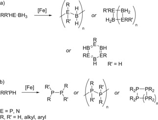
Catalytic dehydrocoupling methodologies, whereby dihydrogen is released from a substrate (or intermolecularly from two substrates) is a mild and efficient method to construct main group element-main group element bonds, the products of which can be used in advanced materials, and also for the development of hydrogen storage materials. With growing interest in the potential of compounds such as ammonia-borane to act as hydrogen storage materials which contain a high weight% of H2, along with the current heightened interest in base metal catalyzed processes, this review covers recent developments in amine and phosphine dehydrocoupling catalyzed by iron complexes. The complexes employed, products formed and mechanistic proposals will be discussed.

Keywords: dehydropolymerization; heterogeneous catalysis; homogeneous catalysis; iron; main group elements.


Figures

Scheme 1
Scheme 1
General scheme for a dehydrocoupling reaction.
Scheme 2
Scheme 2
Thermally‐induced dehydrocoupling of ammonia and diborane led to borazine, which is depicted using Stock's original representation of the molecule. Insert: formal structure of borazine (1).
Figure 1
Figure 1
Structure of the compounds synthesized by Burg and Wagner.
Scheme 3
Scheme 3
Conditions used by Baker and co‐workers to dehydrocouple ammonia‐borane using 4, showing the original proposed product distribution.
Figure 2
Figure 2
a) Structure of the pre‐catalysts and ligands used by Sonnenberg and Morris, where the iron complex of 8 was prepared in situ using FeBr2 or [Fe(H2O)6][BF4]2. b) Examples of the types of poly(borazylene) (9) and cross‐linked poly(borazylene) (10) structures that can be formed during catalysis.
Scheme 4
Scheme 4
The liquid H2 storage system developed by Liu and co‐workers.
Scheme 5
Scheme 5
Products of various amine‐borane DHC reactions catalyzed by 14. The reaction employs a medium pressure Hg lamp.
Scheme 6
Scheme 6
Ammonia‐borane forms a mixture of cyclic products.
Scheme 7
Scheme 7
a) Iron carbonyl dimers form nanoparticles which undertake DHC, with the amino‐borane product (Me2N=BH2) being cyclized off‐metal. b) In contrast the mononuclear iron complex 22 appears to be homogeneous. c) Proposed reaction mechanism using 22. In both reactions, photoactivation takes place using a medium pressure Hg lamp.
Figure 3
Figure 3
Complexes used by the Baker group in their publication in 2012.
Figure 4
Figure 4
Structure of poly(aminoborane).
Figure 5
Figure 5
Structure of the complexes used by Guan.
Scheme 8
Scheme 8
Proposed catalytic cycle for DHC using pre‐catalyst 30.
Scheme 9
Scheme 9
Liu and Wang's postulated catalytic cycle from DFT calculations.
Figure 6
Figure 6
Structure of the Fe(I) amido complexes and Fe(0) complex (34) used by Grützmacher and co‐workers.
Scheme 10
Scheme 10
Catalytic cycle for the dehydrogenation of alcohols with catalyst 35 proposed by Schneider.
Scheme 11
Scheme 11
Schneider's ammonia‐borane DHC catalytic cycle including catalyst deactivation product, 37.
Figure 7
Figure 7
The range of diiron complexes used in the study by Darensbourg and Bengali.
Scheme 12
Scheme 12
Postulated catalytic cycle for dimethylamine‐borane DHC using 38.
Scheme 13
Scheme 13
The complex used by Manners and co‐workers with optimized conditions for diphenylphosphine‐borane DHC.
Figure 8
Figure 8
Structure of the pre‐catalysts used for the polymerization of phosphine‐boranes.
Scheme 14
Scheme 14
An intramolecular iron‐hydride interaction was observed when 39 was irradiated.
Scheme 15
Scheme 15
Manners’ catalytic cycle for phosphine‐borane DHC.
Scheme 16
Scheme 16
Phosphine‐borane DHC using Fe(II) β‐diketiminate complex 38.
Scheme 17
Scheme 17
Dehydrocoupling of secondary phosphines using pre‐catalyst 38.

References

    1. For reviews covering all aspects of main group dehydrocoupling refer to:
    1. Zybill C. E. and Liu C. Y., Synlett 1995, 687–699;
    1. Gauvin F., Harrod J. F., Woo H. G. in Catalytic dehydrocoupling: A general strategy for the formation of element-element bonds, Vol. 42 Eds.: F. G. A. Stone and R. West, Academic Press Limited, London, 1998, pp. 363–405;
    1. Harrod J. F., Coord. Chem. Rev. 2000, 206, 493–531;
    1. Kawakami Y., Li Y., Designed Monomers and Polymers 2000, 3, 399–419;

LinkOut - more resources