Review
. 2018 May 21;47(10):3433-3469.
doi: 10.1039/c7cs00818j.

Protein cage assembly across multiple length scales

Affiliations
Review

Protein cage assembly across multiple length scales

William M Aumiller et al. Chem Soc Rev. .

Abstract

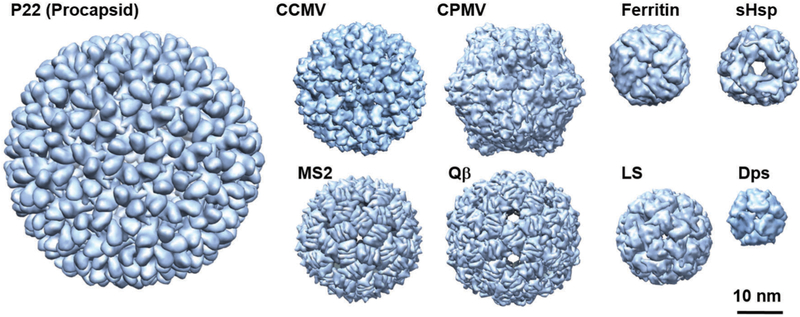
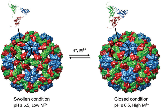
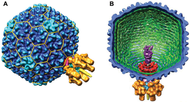
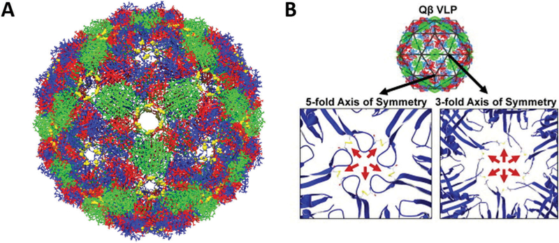
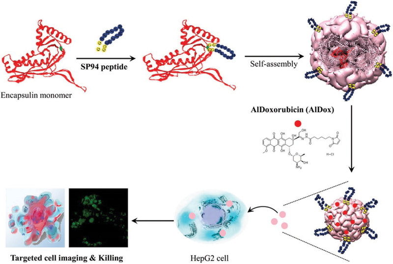
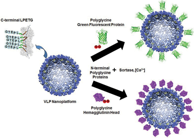
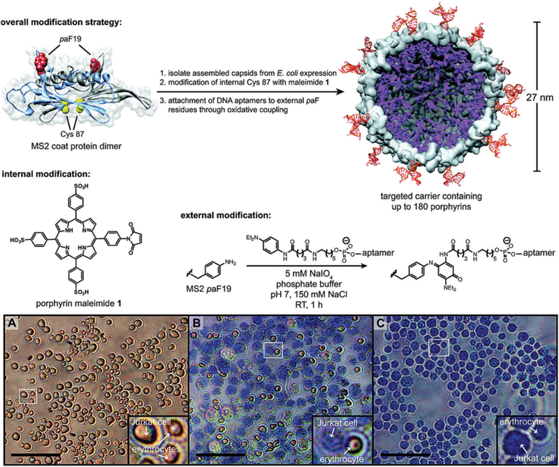
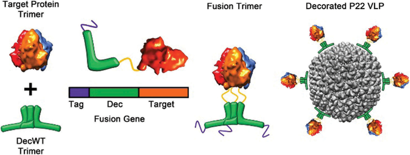
Within the materials science community, proteins with cage-like architectures are being developed as versatile nanoscale platforms for use in protein nanotechnology. Much effort has been focused on the functionalization of protein cages with biological and non-biological moieties to bring about new properties of not only individual protein cages, but collective bulk-scale assemblies of protein cages. In this review, we report on the current understanding of protein cage assembly, both of the cages themselves from individual subunits, and the assembly of the individual protein cages into higher order structures. We start by discussing the key properties of natural protein cages (for example: size, shape and structure) followed by a review of some of the mechanisms of protein cage assembly and the factors that influence it. We then explore the current approaches for functionalizing protein cages, on the interior or exterior surfaces of the capsids. Lastly, we explore the emerging area of higher order assemblies created from individual protein cages and their potential for new and exciting collective properties.


Conflict of interest statement

Conflicts of interest

There are no conflicts of interest to declare.

Figures

Fig. 1
Fig. 1
Space filling models of some protein cages discussed in this review. P22 procapsid (56 nm diameter, T = 7) PDBI: 3IYI, CCMV (28 nm, T = 3) PDB: 1CWP, CPMV (30 nm, pseudo T = 3) PDB: 1NYZ, MS2 (27 nm, T = 3) PDB: 2MS2, Qβ (30 nm, T = 3) PDB: 1QBE, ferritin (12 nm) PDB: 2FHA, sHsp (12 nm) PDB: 1SHS, LS (15 nm, T = 1) PDB: 1RVV, and Dps (9 nm) PDB: 1QGH. These images were reproduced using UCSF Chimera (http://www.cgl.ucsf.edu/chimera) from the Resource for Biocomputing, Visualization, and Informatics at the University of California (supported by NIH RR-01081).
Fig. 2
Fig. 2
Cryo EM reconstruction images of the swollen and closed forms of CCMV. The swollen condition is triggered upon raising the pH to above ~6.5 and lowering the Ca2+ concentration. The swelling occurs at the quasi 3-fold axes to form ~2 nm pores and increases the particle size by ~10%. Figure reproduced from ref. with permission from Wiley, copyright 2007.
Fig. 3
Fig. 3
(A) A surface volume reconstruction image of the infectious P22 virion. The T = 7 organization is indicated by the yellow lattice cage. The portal complex is located at one of the 5-fold vertices. CP (gp5) is in dark blue. (B) A cutaway interior view of the infections P22 virion. The gene products of the tail machinery are shown in different colors: gp1 (red), gp4, (magenta), gp7, 16, and 20 (purple), gp9 (orange), gp10 (light blue), and gp26 (yellow). Figure reproduced from ref. with permission from AAAS, copyright 2006.
Fig. 4
Fig. 4
(A) Chimera reconstruction of bacteriophage Qβ with A chains colored red, B chains colored blue, and C chains colored green. The Cysteine residues C74 and C80 that form disulfide bonds are labeled in yellow. PDB: 1QBE (B) the locations of the disulfide bonds along the FG loop are highlighted (red arrows), both along the 5-fold and 3 fold axes of symmetry. Part B reproduced from ref. with permission from Elsevier, copyright 2011.
Fig. 5
Fig. 5
Density map of the TMV structure obtained by cryoEM. (a) Density of a single turn composed of 16 subunits (b) 3D construction image of a TMV rod. Figure adapted from ref. with permission from Elsevier, copyright 2007.
Fig. 6
Fig. 6
Ribbon diagrams of exterior surface of view of (A) human heavy-chain ferritin (PDB: 2FHA) looking down from 4 fold axis (left) and 3 fold axis,(B) ferritin from Archaeoglobus fulgidus (PDB: 1S3Q) looking down from 3 fold axis, and (C) Dps from Sulfolobus sofataricus (PDB: 2CLB) looking down from 3 fold axis. These images were reproduced using UCSF Chimera (http://www.cgl.ucsf.edu/chimera) from the Resource for Biocomputing, Visualization, and Informatics at the University of California (supported by NIH RR-01081).
Fig. 7
Fig. 7
Structures of member capsid proteins of the PRD1-adenovirus lineage. (a) The structures are STIV (Sulfolobus turreted icosahedral virus, cyan), human adenovirus (purple), bacteriophage PRD1 (green), bacteriophage PM2 (blue), and Paramecium bursaria chlorella virus type 1 (PBCV-1, red). (b) The structure of the PRD1 virion, which forms a T = 25 capsid. The inset shows the trimeric capsomer with the individual monomers indicated. Figure adapted from ref. with permission from Nature Publishing Group, copyright 2008.
Fig. 8
Fig. 8
HK97 and related protein structures with common features high-lighted. (A) HK97 in the immature state (PDB: 3E8K), (B) P22, (C) T4, (PDB: 1YUE), (D) BPP-1 (PDB: 3J4U), and (E) P-SSP7 (PDB: 2XD8). The common features are N-arm (red), E-loop (yellow), P-domain (green), A-domain (cyan), β-hinge (orange). (F) An electron density map of the HK97 capsid with capsomers (both the hexamer [6-asymmetric subunits, multicolored] and the pentamer [red]) indicated. Parts A–E adapted from ref. with permission from Elsevier, copyright 2015. Part F adapted from ref. with permission from Nature Publishing Group, copyright 2009.
Fig. 9
Fig. 9
Scheme of P22 assembly. Figure adapted from ref. with permission from Elsevier, copyright 2010.
Fig. 10
Fig. 10
A model for CPMV virion and empty VLP assembly. Pentamers are made up of large (L, green) and small (S, blue) subunits. The C-terminal extension is represented by the violet circle. RNA is the orange rectangle. In RNA free assembly (upper panel) C-terminal cleavage is slow. In the presence of RNA (bottom panel), the C-terminal extension is cleaved fast and RNA binds at the 2-fold axis. Figure reproduced from ref. with permission from Nature Publishing Group, copyright 2015.
Fig. 11
Fig. 11
Assembly of a capsid around a polyelectrolyte cargo (e.g. a nucleic acid). Red is the nucleic acid cargo and blue is the coat protein. At low ionic strength (stronger coat–cargo interactions) and weak cargo–cargo interactions, an en masse mechanism is favored (A). The nucleation and growth mechanism is favored when coat–cargo interactions are weaker (higher ionic strength) and stronger coat–coat interactions. Figure adapted from ref. with permission from Elsevier, copyright 2014.
Fig. 12
Fig. 12
Proposed model for the assembly of ferritin by Sato et al. Each dimer unit is depicted as a different color. In this mechanism, hexamers (a trimer of dimers) can form directly from dimers, but also from a tetramer and a dimer. In the final step, 2 dodecamers form the 24-mer cage. Figure reproduced from ref. with permission from the American Chemical Society, copyright 2016.
Fig. 13
Fig. 13
The range of particle morphologies possible of CCMV assembly as a function of pH and ionic strength. (A) Phase diagram of protein assembly outcome over a range of pH and ionic strength. Samples were buffered with sodium cacodylate (red) or sodium citrate (black). The blue area represents conditions of assembly from ref. and . (B) Electron microscopy images of different observed morphologies. (a) Multishelled structures are dominant at pH 4.8 and I = 0.01. (b) Tubular structure observed at pH 6.0 and I = 0.01 (c) Dumbbell shaped particles at pH 7.5, 0.001 M cacodylate buffer.(d) Single walled shells at pH 4.67 and 0.1 M acetate buffer and I = 0.1 Figure reproduced from ref. with permission from the American Chemical Society, copyright, 2009.
Fig. 14
Fig. 14
Model of the engineered fusion protein and the resulting octahedral structure formed. (a) The fusions are composed of a trimeric protein (KDPGal aldolase, green) and a dimeric protein (FkpA, orange) with a four residue helical linker (blue). The lines represent the three-fold (cyan) and two-fold (magenta) axes. (b) The 24-mer cage with octahedral symmetry, with the symmetry axes shown. (c) 2D class averages of the 24-mer and 12-mer obtained after aligning, clustering, and average particles from several particles (left) which are consistent with calculated projections (center). The 3D atomic models (right) are also included. Figure reproduced from ref. with permission from Nature Publishing Group, copyright 2014.
Fig. 15
Fig. 15
(A) Schematic illustration of magnetite (or maghemite) nanoparticle synthesis in ferritin. Magnetite nanoparticles can be formed and sequestered inside of ferritin even though temperature and pH used for this synthesis are far from physiological condition. TEM image on the right shows magnetite nanoparticles with approximately 6 nm in diameter synthesized inside of ferritin. (B) TEM image of a TMV containing an approximately 250 nm long nickel nanowire in the central channel. Part B reproduced from ref. with permission from Wiley, copyright 2004.
Fig. 16
Fig. 16
Atom-transfer radical polymerization (ATRP) can be used for high loading of Gd–DTPA within the P22 VLP. In the first step, an internal cysteine is labeled with a radical initiator (2-bromoisobutyryl maleimide, 1). Next poly-2-aminoethyl methacryalate (AEMA) is formed via ATRP. In the last step, the amino groups can be modified with FITC dye (2) or GD-DTPA-NCS (3). Figure reproduced from ref. with permission from Nature Publishing Group, copyright 2012.
Fig. 17
Fig. 17
(A) Proposed mechanism of BMV virus-like particle (VLP) assembly around a gold nanoparticle (NP). First, electrostatic interaction leads to the formation of a disordered capsid protein (CP)–gold NP complex. The second step is a crystallization phase in which the protein–protein interactions result in the formation of a regular capsid. (B–D) Three-dimensional reconstruction (using negative stain data) of BMV VLP self-assembled around gold NPs with (B) 6 nm, (C) 9 nm, and (D) 12 nm diameter gold NPs. Structure and size of reconstituted models of (B), (C), and (D) resemble to a T = 1, a pseudo T = 2, and T = 3 models of BMV capsids, respectively. Part A reproduced from ref. with permission from the American Chemical Society, copyright 2006. Part B reproduced from ref. with permission from the National Academy of Sciences, copyright 2007.
Fig. 18
Fig. 18
An example of a direct encapsulation of enzyme into a capsid by molecular recognition. A Rev-tagged enzyme is bound to the interior of the capsid via an RNA with a Rev aptamer and a Qβ genome packaging hairpin that that is bound to the interior of the capsid. Figure reproduced from ref. with permission from Wiley, copyright 2010.
Fig. 19
Fig. 19
The morphologies of P22 and the mapping of cargo location within them. (A) P22 procapsid (PC) undergoes a morphological change to a more angular expanded (EX) from upon heating, mimicking the structure of the native virion. The internal volume increases approximately 35% and porosity of the capsid decreases. Heating further forms the wiffleball (WB) morphology, where pentamers are removed leaving large holes in the capsid wall. (B) The central sections of three-dimensional reconstructions of the empty P22 and CelB-P22. The darker region on the interior lumen of the capsid indicates higher density, caused by the presence of the bound cargos. The arrows indicate the increased density from the SP-C terminal region of the SP and the CelB-SP binding to the capsid interior. (C) Reconstructions of the EX forms with cargo. Decreased electron density reveals that the cargos are no longer bound to the capsid and can freely move within the entire capsid interior volume. Part A adapted from ref. with permission from The Royal Society of Chemistry. Part B and C reproduced from ref. with permission from The Royal Society of Chemistry.
Fig. 20
Fig. 20
Encapsulation of an active hydrogenase within a P22 VLP (P22-Hyd-1). (A) Scheme showing expression of both subunits of the hydrogenase as fusions with truncated scaffold protein (hyaA-SP and hyaB-SP) under IPTG control with coat protein (CP) in a separate plasmid under L-arabinose control. The result is P22 capsid with both subunits packaged within it. Structures are PDB: 3USE (E. coli hydrogenase-1), PDB: 2XYY (P22 procapsid), PDB: 2GP8 (scaffold protein binding domain). (B) Hydrogen is assayed via gas chromatography using methyl viologen (MV+•) as the electron transfer mediator and an electron source (dithionite or electrochemical reduction). (C) TEM image (negative staining) of P22-Hyd particles. (D) Specific activity of P22-Hyd at varying concentrations of methyl viologen. The enzyme activity follows Michealis–Menten kinetics. (E) Specific activity traces of P22-Hyd-1 (black triangles) and free Hyd-1 (gray squares) shows a marked increase in activity of the P22 encapsulated Hyd-1 compared to Hyd-1 in solution. Figure adapted from ref. with permission from Nature Publishing Group, copyright 2016.
Fig. 21
Fig. 21
Functionalization and targeting of encapsulin. Encapsulin is genetically modified to contain the targeting ligand (SP94) and is assembled to form a protein cage. An anticancer drug aldoxorubicin was delivered to the HepG3 cells, resulting in cytotoxicity to the cells. Figure reproduced from ref. with permission from the American Chemical Society, copyright 2014.
Fig. 22
Fig. 22
A modular approach to presentation of cargo on the exterior of a protein cage. The CP of P22 was genetically engineered to contain a LPETG amino acid sequence at the C-terminal that can be covalently bound to a poly glycine sequence an N-terminal of cargo (here, GFP or hemagglutinin head) via the enzyme sortase. This modular approach allows for many different cargo types to be presented without the need for redesigning the modified CP sequence. Figure reproduced from ref. with permission from the American Chemical Society, copyright 2017.
Fig. 23
Fig. 23
Overall scheme for the construction of a dually functionalized recombinant bacteriophage MS2. Interior cysteines were modified with porphyrin (purple); exterior p-aminophenylalanine were modified with DNA aptamers (~20 per particle). (A) Live control cells showing the difference in size and shape between Jurkat cells and red blood cells (RBCs). (B) Exposure of the cells to the functionalized MS2 capsids to light for 20 minutes results in selective killing of Jurkat cells as indicated by trypan blue staining. RBCs are left unharmed. (C) Positive control showing death of both cell types induced by 30% ethanol. Scale bars are 100 0μm. Figure adapted from ref. with permission from the American Chemical Society, copyright 2010.
Fig. 24
Fig. 24
Presentation of a target protein trimer CD40L (PDB 1ALY) on a P22 VLP exterior. The Dec trimer is pictured in green. A polyhistidine tag (purple) is used for purification. The CD40L is genetically fused to the C-terminus of Dec and presented as a trimer. Dec binds to P22 at the quasi 3-fold axes to present the CD40L on the exterior. Figure reproduced from ref. with permission from the American Chemical Society, copyright 2015.
Fig. 25
Fig. 25
(A) Schematic of nanografting and virus deposition process. (A) A Ni-NTA terminated surface is created at specific locations on a gold substrate (red lines) to allow for deposition of His-tagged CPMV (yellow spheres) via Ni(ii) chelation. (B–E) AFM images showing the coverage of the CPMV on the substrate as well as the increasing order observed by increases in virus concentration (flux) and increasing inter-viral attractive interaction (increasing PEG concentration). (B) At a condition of low flux and weak inter-viral attractive interaction (0 wt% PEG), His-CPMV attaches almost exclusively to the Ni-NTA line, but the coverage is low. (C) At higher flux with weak interaction, His-CPMV still exclusively attaches to the line, but with increased coverage. (D and E) As the inter-viral interaction is increased (by addition of 1 wt% PEG), virus assembly spreads outward from the lines, and clusters of viruses lie between the lines.(F) Higher resolution AFM image of condition (C), showing His-CPMV alignment at a single capsid width. (G) Higher resolution image of condition (E), showing ordered packing of virus capsid on the Ni-NTA line. Figure reproduced from ref. with permission from the American Chemical Society, copyright 2006.
Fig. 26
Fig. 26
(A) Superlattice formation of positively charged gold nanoparticles (AuNP) and negatively charged CCMV at different Debye screening lengths, k−1, (adjusted by NaCl concentration), AuNP/CCMV mass ratios (top) and pH (bottom) determined by small angle X-ray scattering (SAXS). At a given pH, the superlattice is formed only in a narrow NaCl concentration window (Region 2), which is shifted to smaller k−1 (i.e. higher NaCl concentration) when the pH is increased. Superlattice formation is possible only when the pH is higher than pI of CCMV (pH = 3.8). High NaCl concentration screens the electrostatic interaction between CCMV and AuNP, resulting in non-assembly of the particles (Region 3). (B) Two-dimensional (inset) and integrated one-dimensional SAXS data obtained from a CCMV superlattice (sample 2 in (A)) (top). The experimental scattering pattern (black trace) matches well with the respective theoretical scattering pattern of an AB8FCC-type structure (red and green traces). Crystalline superlattices are also observed with cryo-TEM (bottom). The particles arrange into an AB8FCC type lattice, where CCMV (blue) adopts an FCC structure and the voids between the CCMVs are filled with eight AuNPs (yellow) as shown in inset. (C) Crystal structure models and lattice parameters of CCMV–avidin, CCMV–G6 PAMAM dendrimer and CCMV–Au nanoparticle superlattice. Superlattices with different structures are yielded depending on linker molecules, which mediate assembly of CCMV. Parts A and B reproduced from ref. with permission from Nature Publishing Group, copyright 2013. Part C adapted from ref. with permission from Nature Publishing Group, copyright 2014.
Fig. 27
Fig. 27
Schematic illustration for metal/linker-directed self-assembly of ferritin into three-dimensional crystals. Surface exposed Zn2+ binding sites are engineered at 3-fold symmetry (C3) sites of ferritin by mutating threonine 122 to histidine (T122H). In the presence of ditopic organic linkers, the T122H ferritin mutant forms a BCC lattice through coordination of ferritins at the C3 sites. On the other hand, in the absence of such ditopic linkers, the mutant forms a FCC lattice, which ferritin typically crystalized into, through coordination at 2-fold symmetry (C2) sites. Figure reproduced from ref. with permission from the American Chemical Society, copyright 2015.
Fig. 28
Fig. 28
(A) TEM images of P22 mixed with a ditopic linker derived from Dec (left) or wild type (wt) Dec (right). In the case of P22 with ditopic Dec linker, large clusters of micrometer to tens of micrometers in size, which composed of P22 VLP, were observed. In the case of P22 with wtDec, each VLP were well dispersed and no cluster of VLP was observed. (B) Quartz crystal microbalance (QCM) resonance frequency changes upon alternate injection of P22, ditopic Dec linker and wtDec on a gold coated QCM sensor. The decrease in resonance frequency corresponds to the increase in mass on the sensor due to the deposition of the proteins. Layer-by-layer deposition was demonstrated through the alternative addition of P22 and ditopic Dec linker. Addition of wtDec caps the deposited layer and passivates from further attachment of P22 because it has only one binding site for P22. The cartoon on the right depicts observed layer-by-layer deposition. Figure adapted from ref. with permission from Wiley, copyright 2015.

References

    1. Johnson JE and Chiu W, Curr. Opin. Struct. Biol, 2000, 10, 229–235. - PubMed
    1. Douglas T and Young M, Science, 2006, 312, 873–875. - PubMed
    1. Harrison PM and Arosio P, Biochim. Biophys. Acta, Bioenerg, 1996, 1275, 161–203. - PubMed
    1. Uchida M, Kang S, Reichhardt C, Harlen K and Douglas T, Biochim. Biophys. Acta, 2010, 1800, 834–845. - PMC - PubMed
    1. Horwich AL, Fenton WA, Chapman E and Farr GW, Annu. Rev. Cell Dev. Biol, 2007, 23, 115–145. - PubMed