Review
. 2018 Apr 3;47(7):2454-2484.
doi: 10.1039/c7cs00404d.

Optogenetically controlled protein kinases for regulation of cellular signaling

Affiliations
Review

Optogenetically controlled protein kinases for regulation of cellular signaling

Anna V Leopold et al. Chem Soc Rev. .

Abstract

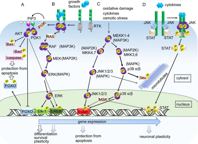
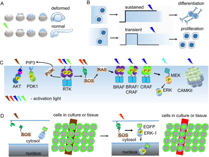
Protein kinases are involved in the regulation of many cellular processes including cell differentiation, survival, migration, axon guidance and neuronal plasticity. A growing set of optogenetic tools, termed opto-kinases, allows activation and inhibition of different protein kinases with light. The optogenetic regulation enables fast, reversible and non-invasive manipulation of protein kinase activities, complementing traditional methods, such as treatment with growth factors, protein kinase inhibitors or chemical dimerizers. In this review, we summarize the properties of the existing optogenetic tools for controlling tyrosine kinases and serine-threonine kinases. We discuss how the opto-kinases can be applied for studies of spatial and temporal aspects of protein kinase signaling in cells and organisms. We compare approaches for chemical and optogenetic regulation of protein kinase activity and present guidelines for selection of opto-kinases and equipment to control them with light. We also describe strategies to engineer novel opto-kinases on the basis of various photoreceptors.


Conflict of interest statement

CONFLICTS OF INTEREST

The authors declare no conflict of interest.

Figures

FIGURE 1
FIGURE 1. The structural basis for the activation of protein kinases
Protein kinases in inactive state are in gray and activated protein kinases are in violet. (A) Left: Schematic depiction of the bilobal structure of eukaryotic protein kinases. Right: The bilobal structure of PKA (PDB ID: 2CPK), in rainbow coloring. (B) In the inactive state, PDK1 interacting fragment (PIF-tide) binds to PIF-pocket of the same kinase molecule. Upon kinase activation, PIF-tide dissociates and binds to PIF pocket of another kinase molecule. (C) Activation of CDK kinases through their interaction with cyclins. Left: N-terminal αC-helix (black) locks the catalytic cleft and inactivates kinase. Right: CMGC insert-mediated interaction of the CDK kinase with the cyclin dissociates αC-helix, disrupts blockage of the catalytic cleft and makes it accessible for the phosphorylation that results in kinase activation. (D) Regulation of MAPK kinases. In the inactive state, CMGC motif (red) is bound to kinase C-lobe, whereas upon activation it interacts with the N-terminal D-motif (docking motif) of the other MAPK-kinase. (E) In the inactive state, of CAMK, inhibitory C-terminal motif (shown in red) locks catalytic center, whereas binding to calmodulin releases this lock and activates catalytic center. (F) Left: Interaction with growth factors lead to dimerization, transphosphorylation of kinase cytoplasmic domains and activation of downstream signaling. Right: Binding of insulin to insulin receptor causes their conformational changes and activation. Ig-like extracellular domains of RTKs are shown in green. (G) Regulation of SFK non-receptor tyrosine kinases through inhibitory phosphate at the C-terminus of the catalytic kinase domain. SH2 domains are shown in blue. (H) Non-receptor tyrosine kinases: regulation through autoinhibition by different N-terminal inhibitory domains. N-terminal inhibitory domains are shown in blue. (I) JAK kinases are attached to cytokine receptors (green). Cytokine receptors dimerize upon interaction with cytokines (blue), and JAK kinases transphosphorylate each other and phosphorylate STAT transcription factors bound to cytokine receptors.
FIGURE 2
FIGURE 2. The major protein kinase signaling pathways
From left to right: (A) Prosurvival action of AKT signaling: AKT phosphorylates and inhibits pro-apoptotic proteins in the cytosol and phosphorylates and causes dislocation of the FOX3O transcription factor from the nucleus; (B) Signaling by growth factor receptors leads to the activation of the prosurvival MAPK ERK1/2 pathway and to the induction of prosurvival transcription factors; (C) Stress factors lead to the activation of the stress-induced MAPK pathways JNK1/2/3 and p38, which leads to the induction of pro-apoptotic c-Jun activation and phosphorylation of tau protein; and (D) Activation of the JAK-STAT pathway by cytokines leads to the dimerization of cytokine receptors, phosphorylation of the associated with them JAK kinases, subsequent phosphorylation of STAT transcription factors and dissociation of the phosphorylated STAT transcription factors in the cell nucleus.
FIGURE 3
FIGURE 3. Photoreceptors used for the engineering of opto-kinases
(A) The structure of the Neurospora crassa LOV protein Vivid in its signaling state (PDB ID: 3RH8). N-terminal extensions important for dimer formation are shown in magenta. FAD cofactor is shown. (B) Crystal structure of the LOV2 domain of Avena sativa phototropin-1 (AsLOV2). N-terminal (A’α) and C-terminal helices (Jα) are shown in magenta. FAD cofactor is shown. In the dark state, helices are packed on the outer face of a five-stranded antiparallel β-sheet that adopts the PAS fold (PDB ID: 2V0U), (C) Crystal structure of cryptochrome-1, which is the closest homolog of cryptochrome-2 from Arabidopsis thaliana (1U3D). Both cryptochromes are involved in signaling and share 60% of amino acid identity. N-terminal αβ domain is in brown, large mainly unstructured linker region in magenta, and C-terminal α domain in green. (D) The structure of bright dimeric Dronpa (2Z6Y). Flexible β7-strand is in magenta. Autocatalytically formed from GYC amino acids chromophore is shown. (E) Crystal structure of phytochrome from Xanthomonas campestris (PDB ID: 5AKP). PAS domain is shown in green, GAF in cyan, PHY in magenta and HisK in brown. Extended α-helices that propagate the signal from the GAF to the HisK domain are in black. BV chromophore is shown. (F) Crystal structure of transcriptional regulator CarH from Thermus thermophilus (PDB ID: 5CK8F). N-terminal DNA-binding HTH domain is in brown and C-terminal domain that binds B12 cofactor in green. Chromophores and cofactors in all panels are shown as spheres with carbon in gray, oxygen in red, nitrogen in blue, sulfur in yellow and phosphorus in orange.
FIGURE 4
FIGURE 4. The general strategies to engineer opto-kinases
(A) Homodimerization. Upon blue-light illumination, LOV domains form a homodimer that causes activation of the receptor tyrosine kinase (RTK). (B) Heterodimerization. Illumination results in CRRY2-CIBN interaction, recruitment of constitutively active Akt kinase domain to the PM and downstream signaling. (C) Clustering. CRY2 fused to the receptor targeting domain is monomeric in darkness and possesses low affinity to RTK. Illumination results in CRY2 oligomerization and increased affinity to RTK. Subsequent receptor clustering activates kinase signaling. (D) Oligomerization. Undocking of Jα helix from the LOV2 core results in uncaging of the peptide and recruitment of Ste5 on the PM through ePDZ–peptide interaction. Ste5 act as the scaffold to assemble multiprotein complex that activates signaling. (E) Uncaging. In the darkness, MEK kinase site is sterically caged between two Dronpa molecules forming the intramolecular homodimer. Illumination results in monomeric Dronpa that correspond to uncaging and psMEK1 activation. (F). Allosteric control. The LOV2 domain is inserted in the loop in the catalytic domain. In darkness then Jα helix is docked on the core of LOV2 it does not interfere with the activity whereas illumination abrogates kinase activity due to Jα undocking. In all panels the red star designates the signaling state of protein kinase.
FIGURE 5
FIGURE 5. Workflow for the development of opto-kinases
Step 1. Choosing of an engineering approach for different groups of mammalian tyrosine and serine-threonine kinases. The kinase groups are indicated on the right side of each arrow. Approaches applicable to engineer light-regulated kinases of each group (clustering, dimerization, etc.) are indicated behind each arrowhead. Step 2. Selection of an optogenetic system. Selection of the optogenetic system depends on the engineering approach. From left to right: the optogenetic systems corresponding to the engineering approaches from tstep 1 are presented. See text for further details and examples. Step 3. Methods allowing to test opto-kinase activity. (i) Immunochemistry: Western blotting using phospho-specific antibodies allows to make a distinction between activated and non-activated states of opto-kinase. Applicable to all kinase groups. (ii) SRE-dependent expression of fluorescent and bioluminescent reporters: a gene of the reporter is cloned after the serum response element (SRE). SRE is activated as a result of activation of MAPK/ERK pathway. Reporter expression corresponds to the level of the pathway activation. Mostly applicable to RTKs and MAPKs. (iii) Use of fluorescent translocation reporters: a fluorescent reporter, such as Erk or PH-Akt, resides in cell cytoplasm. Upon illumination the reporter translocases to the cell membrane or nucleus. Applicable mostly to opto-RTKs, some AGCs and MAPK opto-kinases. (iv) FRET-based sensors: measurements using these ratiometric fluorescent biosensors are applicable to all opto-kinases but provide the lower sensitivity than the other methods. Step 4. Further characterization and optimization of the resulting advanced opto-kinase variant. Opto-kinases can be implemented in studies of cultured cells and in small model animals in vivo. See text for further details and examples.
FIGURE 6
FIGURE 6. Selected biological applications of opto-kinases
(A) Manipulation of zebrafish development with opto-FGFR. Overexpression of active opto-FGFR in darkness caused developmental malformations such as caudalization of the brain. Illumination of embyos with green light caused inhibition of opto-FGFR and normal embryo development. (B) Constant illumination of PC12 cells expressing CIBN-GFP-CAAX and Cry2PHR-mCherry-Raf1 optogenetic pair leads to recruitment of Raf1 to PM and sustained activation of Raf/MEK/ERK cascade. That causes significant neurite outgrowth, whereas light pulses cause transient activation of the cascade and cell proliferation. (C) Interrogation of protein kinase pathways via selective activation of signaling nodes. From left to right: Activation of opto-AKT with blue light; activation of RTKs with blue and red light, and inactivation with green light; Activation and inactivation of opto-SOS with red and NIR light; Separate activation of different RAF isoforms with the help of blue light; Activation of MEK with cyan light; and inactivation of CAMKII with blue light. (D) Selective activation of subpopulation of cells in tissue culture with NIR and light. Left: In darkness and under NIR light opto-SOS kinase is inactive and GFP-ERK reporter is localized in the cytoplasm. Right: Illumination with red light recruits opto-SOS to the PM where it activates MAPK/ERK cascade. This leads to relocalization of EGFP-ERK1 reporter to the nucleus that occurs only in the illuminated cells.

References

    1. Cohen P. Eur J Biochem. 2001;268:5001–5010. - PubMed
    1. Endicott JA, Noble ME, Johnson LN. Annu Rev Biochem. 2012;81:587–613. - PubMed
    1. Wu P, Nielsen TE, Clausen MH. Trends Pharmacol Sci. 2015;36:422–439. - PubMed
    1. Ebisuya M, Kondoh K, Nishida E. Journal of cell science. 2005;118:2997–3002. - PubMed
    1. Ryu H, Chung M, Dobrzynski M, Fey D, Blum Y, Lee SS, Peter M, Kholodenko BN, Jeon NL, Pertz O. Mol Syst Biol. 2015;11:838. - PMC - PubMed

Substances