. 2018 Dec;50(6):2480-2497.
doi: 10.3758/s13428-018-1026-7.

Development and validation of a high-speed stereoscopic eyetracker

Affiliations

Development and validation of a high-speed stereoscopic eyetracker

Annemiek D Barsingerhorn et al. Behav Res Methods. 2018 Dec.

Abstract

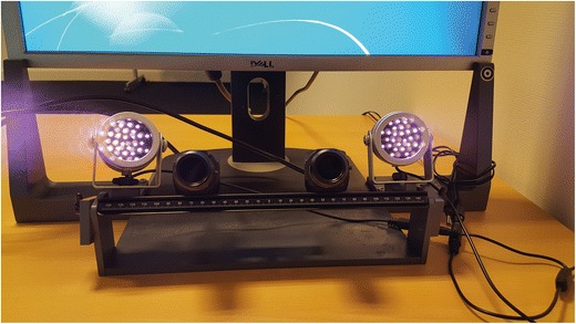
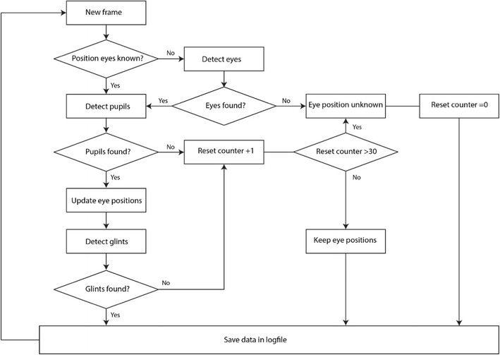
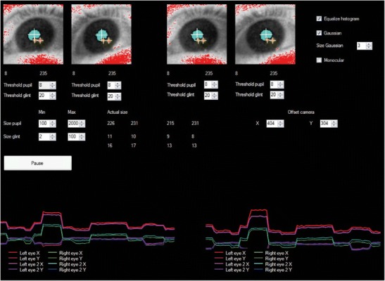
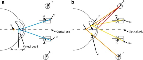
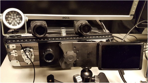
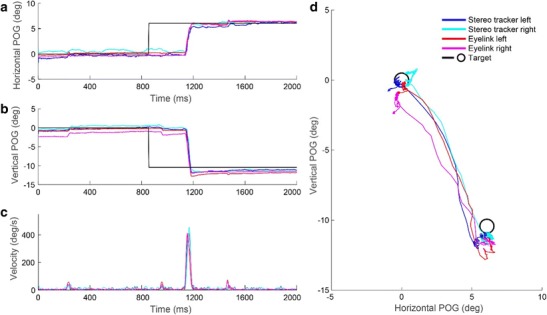
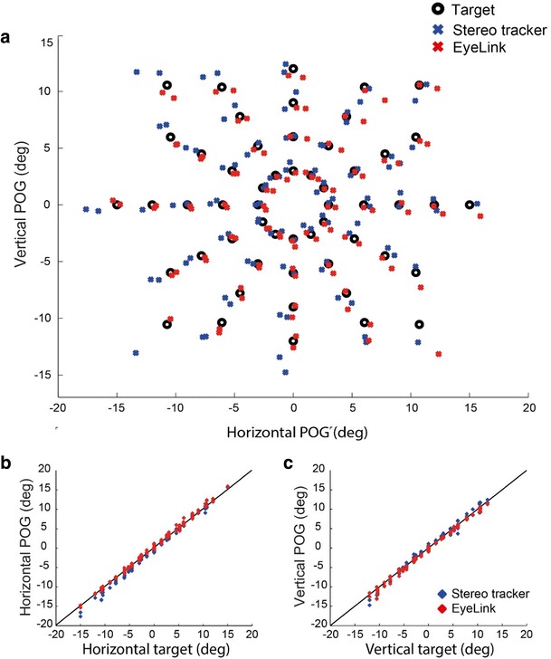
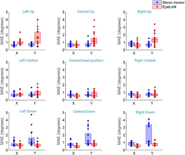
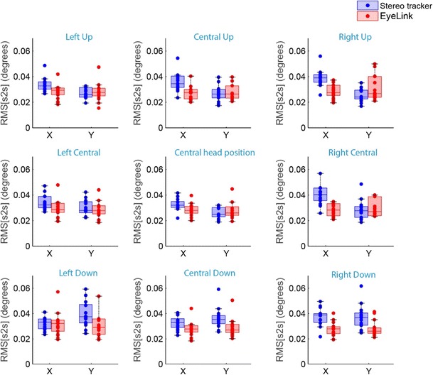
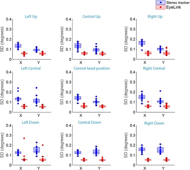
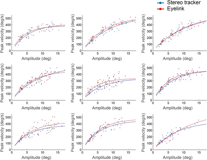
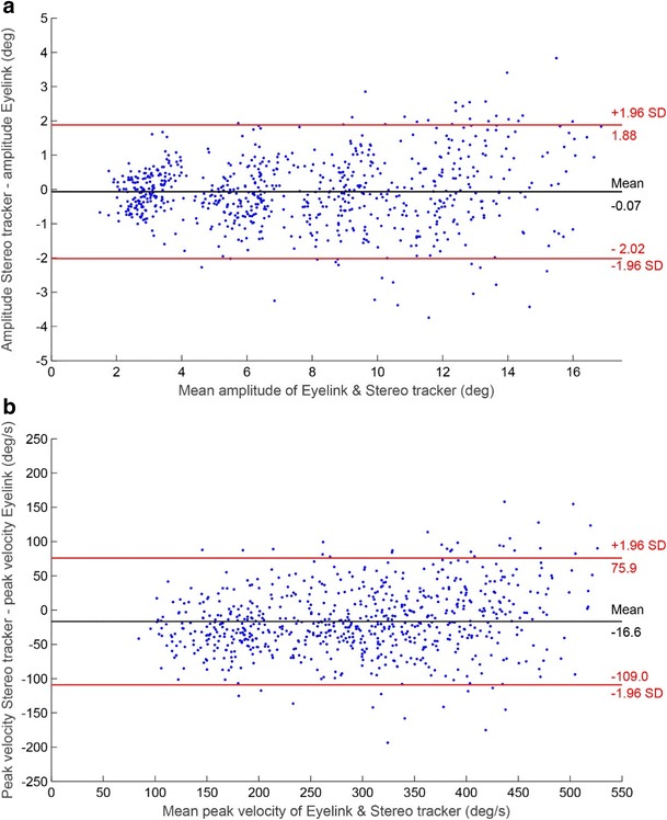
Traditional video-based eyetrackers require participants to perform an individual calibration procedure, which involves the fixation of multiple points on a screen. However, certain participants (e.g., people with oculomotor and/or visual problems or infants) are unable to perform this task reliably. Previous work has shown that with two cameras one can estimate the orientation of the eyes' optical axis directly. Consequently, only one calibration point is needed to determine the deviation between an eye's optical and visual axes. We developed a stereo eyetracker with two USB 3.0 cameras and two infrared light sources that can track both eyes at ~ 350 Hz for eccentricities of up to 20°. A user interface allows for online monitoring and threshold adjustments of the pupil and corneal reflections. We validated this tracker by collecting eye movement data from nine healthy participants and compared these data to eye movement records obtained simultaneously with an established eyetracking system (EyeLink 1000 Plus). The results demonstrated that the two-dimensional accuracy of our portable system is better than 1°, allowing for at least ± 5-cm head motion. Its resolution is better than 0.2° (SD), and its sample-to-sample noise is less than 0.05° (RMS). We concluded that our stereo eyetracker is a valid instrument, especially in settings in which individual calibration is challenging.

Keywords: Eye movements; Eyetracking; Head movement; Stereo eyetracking.


Figures

Fig. 1
Fig. 1
The stereo eyetracking system. The hardware consists of two infrared illuminators and two USB 3.0 cameras connected to a laptop computer
Fig. 2
Fig. 2
Flow chart of the image processing for each camera. First the eyes are detected, after which the pixel coordinates of the pupil and glints are extracted. A reset counter is used to force the software to redetect the eyes only if no pupil or glints are detected in 30 consecutive frames. If only one eye is found, the software continues tracking that eye for 30 frames. After 30 frames, the eyes are redetected in order to continue binocular tracking
Fig. 3
Fig. 3
User interface of the stereo eyetracker. The online image segmentation is visible in the four eye images. The two images on the left are for the left and right eyes of the participant as observed by the left camera. The two images on the right are the participant’s left and right eyes as observed by the right camera. The image segmentations of the pupil (blue) and glints (red) are shown, and the centers of the pupil and glints are indicated with crosshairs. The thresholds for the image segmentation and the size limits of the pupils and glints can be adjusted. Online feedback is provided through the pupil–glint vectors, in the lower panels
Fig. 4
Fig. 4
Ray-tracing diagrams (not to scale), showing a schematic top view of the two cameras, the two infrared illuminators, and one eye. (A) The center of the pupil projections onto each camera (v1 and v2) and the nodal points of those cameras (o1 and o2) were used to triangulate the center of the virtual pupil pv. (B) For each illuminator Lj, causing glint u1j in Camera 1 and glint u2j in Camera 2, its virtual image Lj was obtained through triangulation (yellow lines). Subsequently, the center of corneal curvature c was estimated by intersecting the line through illuminator L1 and its virtual image L1 with the line through illuminator L2 and its virtual image L2
Fig. 5
Fig. 5
Experimental setup for the validation study. The stereo tracker was mounted on top of the EyeLink camera
Fig. 6
Fig. 6
Simultaneous records of both eyetracking systems during one trial. (A) Horizontal POG estimations as a function of time. (B) Vertical POG estimations as a function of time. (C) The corresponding vectorial eye velocity traces, calculated after applying a Butterworth filter (8th-order, cutoff 40 Hz) to the position data. (D) 2-D trajectories of the POG estimations. The results for both eyes are shown. The target positions are plotted as black circles
Fig. 7
Fig. 7
Fixation data from one participant at the central head position (both eyes). (A) 2-D target locations and the corresponding 2-D POG estimations from the EyeLink and stereo eyetracker. (B) Horizontal POG estimates plotted against the horizontal target location. (C) Vertical POG estimates plotted against the vertical target location
Fig. 8
Fig. 8
Box plots showing the accuracies of the EyeLink and the stereo eyetracker for the nine different head locations. The mean absolute errors (MAE) for all individual eyes are superimposed (dots)
Fig. 9
Fig. 9
Box plots showing the intersample precision (RMS[s2s]) of the eyetrackers for the nine different head locations. The intersample precisions (RMS[s2s]) for all individual eyes are superimposed (dots)
Fig. 10
Fig. 10
Box plots showing the standard deviations (SD) of the data samples during fixation, as a measure of the precision of the two eyetrackers for the nine different head locations. The SDs for all individual eyes are superimposed (dots)
Fig. 11
Fig. 11
Relationship between the amplitudes of the saccades and their peak velocities as measured with the two systems. Each panel presents the results for the left eye of one participant at the central head position. Each point represents one saccade. The lines represent the fits of the main sequence (Eq. 13)
Fig. 12
Fig. 12
Bland–Altman plots showing the trial-to-trial differences between the stereo eyetracker and the EyeLink, with 95% confidence intervals, for (A) the saccade amplitude and (B) the peak velocity of the saccades. The data are from the central head position, pooled across eyes and participants

Similar articles

Cited by

References

    1. Al-Rahayfeh Amer, Faezipour Miad. Eye Tracking and Head Movement Detection: A State-of-Art Survey. IEEE Journal of Translational Engineering in Health and Medicine. 2013;1:2100212–2100212. doi: 10.1109/JTEHM.2013.2289879. - DOI - PMC - PubMed
    1. Bahill A.Terry, Clark Michael R., Stark Lawrence. The main sequence, a tool for studying human eye movements. Mathematical Biosciences. 1975;24(3-4):191–204. doi: 10.1016/0025-5564(75)90075-9. - DOI
    1. Barsingerhorn AD, Boonstra FN, Goossens J. Optics of the human cornea influence the accuracy of stereo eye-tracking methods: A simulation study. Biomedical Optics Express. 2017;8:189–196. doi: 10.1364/BOE.8.000712. - DOI - PMC - PubMed
    1. Beymer, D., & Flickner, M. (2003). Eye gaze tracking using an active stereo head. In Proceedings of the IEEE Computer Society Conference on Computer Vision and Pattern Recognition (Vol. 2, pp. 451–458). Piscataway, NJ: IEEE Press. 10.1109/CVPR.2003.1211502
    1. Bradski G, Kaehler A. Learning OpenCV. Sebastopol, CA: O’Reilly Media; 2008.

Publication types