

Acuros CTS: A fast, linear Boltzmann transport equation solver for computed tomography scatter - Part I: Core algorithms and validation
- PMID: 29509970
- PMCID: PMC5948176
- DOI: 10.1002/mp.12850
Acuros CTS: A fast, linear Boltzmann transport equation solver for computed tomography scatter - Part I: Core algorithms and validation
Abstract
Purpose: To describe Acuros® CTS, a new software tool for rapidly and accurately estimating scatter in x-ray projection images by deterministically solving the linear Boltzmann transport equation (LBTE).
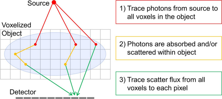
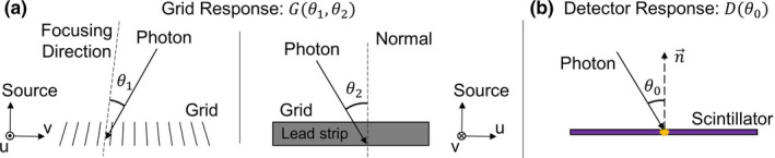
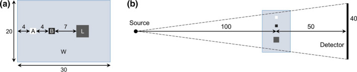
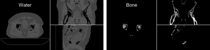
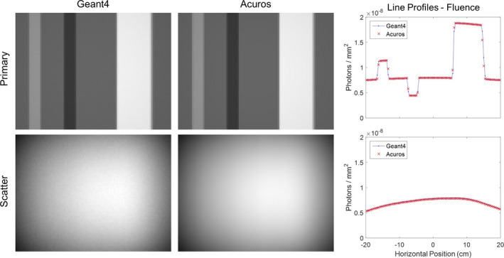
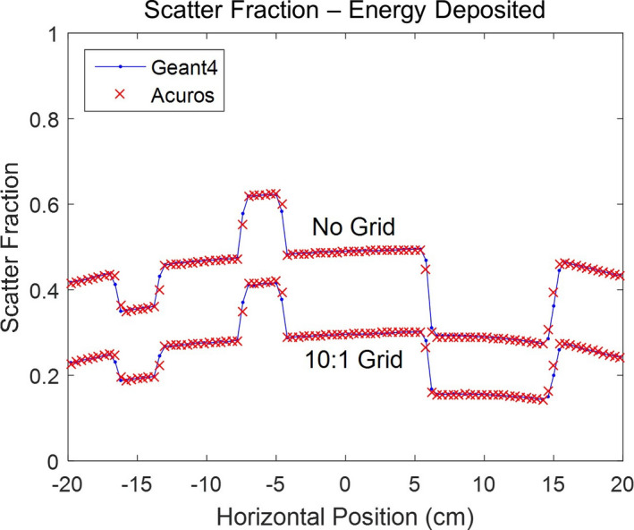
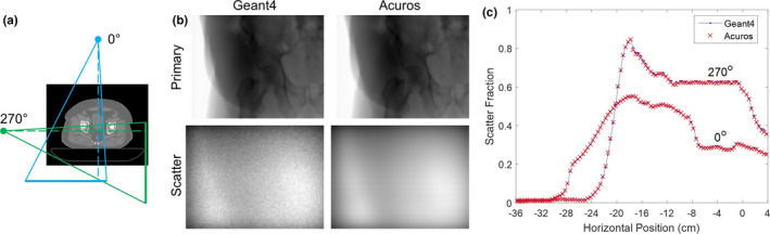
Methods: The LBTE describes the behavior of particles as they interact with an object across spatial, energy, and directional (propagation) domains. Acuros CTS deterministically solves the LBTE by modeling photon transport associated with an x-ray projection in three main steps: (a) Ray tracing photons from the x-ray source into the object where they experience their first scattering event and form scattering sources. (b) Propagating photons from their first scattering sources across the object in all directions to form second scattering sources, then repeating this process until all high-order scattering sources are computed using the source iteration method. (c) Ray-tracing photons from scattering sources within the object to the detector, accounting for the detector's energy and anti-scatter grid responses. To make this process computationally tractable, a combination of analytical and discrete methods is applied. The three domains are discretized using the Linear Discontinuous Finite Elements, Multigroup, and Discrete Ordinates methods, respectively, which confer the ability to maintain the accuracy of a continuous solution. Furthermore, through the implementation in CUDA, we sought to exploit the parallel computing capabilities of graphics processing units (GPUs) to achieve the speeds required for clinical utilization. Acuros CTS was validated against Geant4 Monte Carlo simulations using two digital phantoms: (a) a water phantom containing lung, air, and bone inserts (WLAB phantom) and (b) a pelvis phantom derived from a clinical CT dataset. For these studies, we modeled the TrueBeam® (Varian Medical Systems, Palo Alto, CA) kV imaging system with a source energy of 125 kVp. The imager comprised a 600 μm-thick Cesium Iodide (CsI) scintillator and a 10:1 one-dimensional anti-scatter grid. For the WLAB studies, the full-fan geometry without a bowtie filter was used (with and without the anti-scatter grid). For the pelvis phantom studies, a half-fan geometry with bowtie was used (with the anti-scatter grid). Scattered and primary photon fluences and energies deposited in the detector were recorded.
Results: The Acuros CTS and Monte Carlo results demonstrated excellent agreement. For the WLAB studies, the average percent difference between the Monte Carlo- and Acuros-generated scattered photon fluences at the face of the detector was -0.7%. After including the detector response, the average percent differences between the Monte Carlo- and Acuros-generated scatter fractions (SF) were -0.1% without the grid and 0.6% with the grid. For the digital pelvis simulation, the Monte Carlo- and Acuros-generated SFs agreed to within 0.1% on average, despite the scatter-to-primary ratios (SPRs) being as high as 5.5. The Acuros CTS computation time for each scatter image was ~1 s using a single GPU.
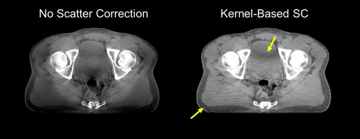
Conclusions: Acuros CTS enables a fast and accurate calculation of scatter images by deterministically solving the LBTE thus offering a computationally attractive alternative to Monte Carlo methods. Part II describes the application of Acuros CTS to scatter correction of CBCT scans on the TrueBeam system.
Keywords: Monte Carlo; cone-beam CT; deterministic calculation; discrete ordinates; finite element; scatter.
© 2018 American Association of Physicists in Medicine.
Conflict of interest statement
All authors were employees of Varian Medical Systems.
Figures
References
-
- Jaffray DA, Siewerdsen JH, Wong JW, Martinez AA. Flat‐panel cone‐beam computed tomography for image‐guided radiation therapy. Int J Radiat Oncol. 2002;53:1337–1349. - PubMed
-
- Orth RC, Wallace MJ, Kuo MD. C‐arm cone‐beam CT: general principles and technical considerations for use in interventional radiology. J Vasc Interv Radiol. 2008;19:814–820. - PubMed
-
- Scarfe WC, Farman AG, Sukovic P. Clinical applications of cone‐beam computed tomography in dental practice. J Can Dent Assoc. 2006;72:75–80. - PubMed
-
- Endo M, Tsunoo T, Nakamori N, Yoshida K. Effect of scattered radiation on image noise in cone beam CT. Med Phys. 2001;28:469–474. - PubMed
-
- Siewerdsen JH, Jaffray DA. Cone‐beam computed tomography with a flat‐panel imager: magnitude and effects of x‐ray scatter. Med Phys. 2001;28:220–231. - PubMed
Publication types
MeSH terms
Grants and funding
LinkOut - more resources
Full Text Sources
Other Literature Sources
Medical
Research Materials
