. 2018 Mar 11;18(3):838.
doi: 10.3390/s18030838.

Research on Flow Field Perception Based on Artificial Lateral Line Sensor System

Affiliations

Research on Flow Field Perception Based on Artificial Lateral Line Sensor System

Guijie Liu et al. Sensors (Basel). .

Abstract

In nature, the lateral line of fish is a peculiar and important organ for sensing the surrounding hydrodynamic environment, preying, escaping from predators and schooling. In this paper, by imitating the mechanism of fish lateral canal neuromasts, we developed an artificial lateral line system composed of micro-pressure sensors. Through hydrodynamic simulations, an optimized sensor structure was obtained and the pressure distribution models of the lateral surface were established in uniform flow and turbulent flow. Carrying out the corresponding underwater experiment, the validity of the numerical simulation method is verified by the comparison between the experimental data and the simulation results. In addition, a variety of effective research methods are proposed and validated for the flow velocity estimation and attitude perception in turbulent flow, respectively and the shape recognition of obstacles is realized by the neural network algorithm.

Keywords: artificial lateral line system; flow field perception; hydrodynamic simulation; neural network; velocity estimation.


Conflict of interest statement

The authors declare no conflicts of interest.

Figures

Figure 1
Figure 1
Schematic of Superficial Neuromasts and Canal Neuromasts.
Figure 2
Figure 2
The results of the meshing and the definition of the axes. (a) The plane mesh; the green area represents the fluid domain and the oval shape represents the carrier. (b) The definition of axes; the dark blue oval shape represents the carrier in the picture.
Figure 3
Figure 3
Pressure distribution of carrier surface at different flow velocity. (a) Dynamic pressure; (b) Static pressure.
Figure 4
Figure 4
The pressure sensitive point on carrier surface.
Figure 5
Figure 5
The surface pressure curve in different angles under 0.5 m/s. (a) A schematic of angle; (b) Dynamic pressure; (c) Static pressure.
Figure 6
Figure 6
Artificial lateral line system. (a) Sensor distribution; (b) 3D modeling. This model includes the shell, sensors and embedded hardware.
Figure 7
Figure 7
Simulation of static obstacle. (a) Cylindrical obstructions; (b) Square obstructions. The circle represents a circular obstacle, the square represents a square obstacle, and the oval shape represents a carrier.
Figure 8
Figure 8
Cylindrical obstructions with diameter of 50 mm. (a) Dynamic pressure; (b) Static pressure.
Figure 9
Figure 9
Cylindrical obstructions with diameter of 100 mm. (a) Dynamic pressure; (b) Static pressure.
Figure 10
Figure 10
Cylindrical obstructions with diameter of 200 mm. (a) Dynamic Pressure; (b) Static Pressure.
Figure 11
Figure 11
Square obstructions with side length of 100 mm. (a) Dynamic Pressure; (b) Static Pressure.
Figure 12
Figure 12
Square obstructions with side length of 100 mm. (a) Dynamic Pressure; (b) Static Pressure.
Figure 13
Figure 13
Cylindrical obstructions with diameter of 100 mm. (a) Dynamic Pressure; (b) Static Pressure.
Figure 14
Figure 14
A schematic of the simulation environment.
Figure 15
Figure 15
Surface pressure distribution with moving carrier with d = 100 mm. (a) Dynamic Pressure; (b) Static Pressure.
Figure 16
Figure 16
Surface pressure distribution with moving carrier with d = 300 mm. (a) Dynamic Pressure; (b) Static Pressure.
Figure 17
Figure 17
The schematic of simulation environment. In the picture, a circle represents a circular obstacle, and the oval represents a carrier.
Figure 18
Figure 18
Surface pressure distribution with static carrier. (a) Dynamic Pressure; (b) Static Pressure.
Figure 19
Figure 19
The process of environmental perception method.
Figure 20
Figure 20
The overall program about control system.
Figure 21
Figure 21
The physical hardware connection of lateral line.
Figure 22
Figure 22
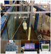
The sink experiment of lateral line.
Figure 23
Figure 23
The process of the No. 1 sensor pressure data.
Figure 24
Figure 24
The results fit of the simulation.
Figure 25
Figure 25
The pressure curve fitting.
Figure 26
Figure 26
The curve fitting of the experimental data.
Figure 27
Figure 27
The amplitude-frequency characteristic of the sensor No. 2.
Figure 28
Figure 28
The results of the simulation. (a) Pressure Difference with v = 0.5 m/s; (b) Pressure Difference with v = 0.3 m/s.
Figure 29
Figure 29
The network topology. In the picture, green indicates the input and output layers, purple indicates the hidden layer, w is the weight, b is the offset, and indicates the activation function.
Figure 30
Figure 30
The output of network. (a) Square obstacle identification; (b) Circle obstacle identification.

Similar articles

Cited by

References

    1. Krahe R., Maler L. Neural maps in the electrosensory system of weakly electric fish. Curr. Opin. Neurobiol. 2014;24:13–21. doi: 10.1016/j.conb.2013.08.013. - DOI - PubMed
    1. Blaxter J.H.S., Fuiman L.A. In: The Mechanosensory Lateral Line: Neurobiology and Evolution. Coombs S., Gorner P., Munz H., editors. Springer Science & Business Media; Berlin, German: 2012. pp. 481–499.
    1. Kanter M.J., Coombs S. Rheotaxis and prey detection in uniform currents by Lake Michigan mottled sculpin. J. Exp. Biol. 2003;206:59–70. doi: 10.1242/jeb.00056. - DOI - PubMed
    1. Gibbs M.A. Lateral line receptors: Where do they come from developmentally and where is our research going. Brain Behav. Evol. 2004;64:163–181. doi: 10.1159/000079745. - DOI - PubMed
    1. Hoekstra D., Janssen J. Non-visual feeding behavior of the mottled sculpin, Cottus bairdi, in Lake Michigan Environ. Biol. Fishes. 2006;12:111–117. doi: 10.1007/BF00002763. - DOI