

Finite element analysis of compression fractures at the thoracolumbar junction using models constructed from medical images
- PMID: 29545839
- PMCID: PMC5841061
- DOI: 10.3892/etm.2018.5848
Finite element analysis of compression fractures at the thoracolumbar junction using models constructed from medical images
Abstract
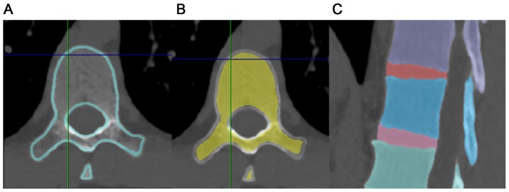
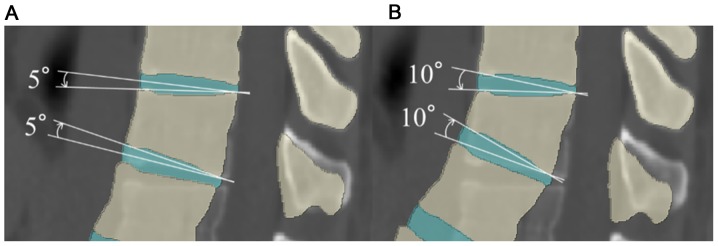
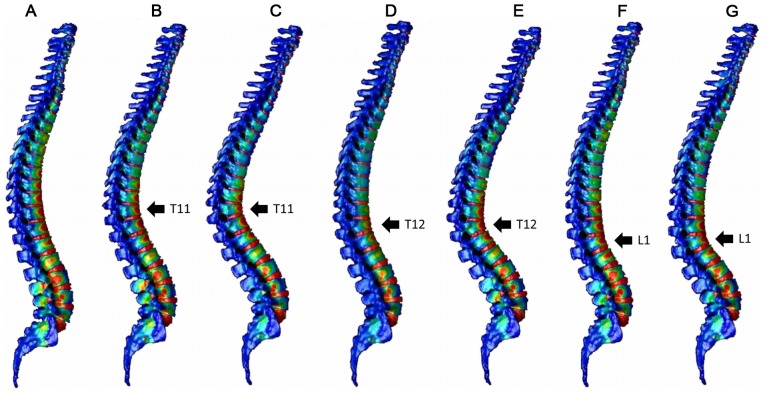
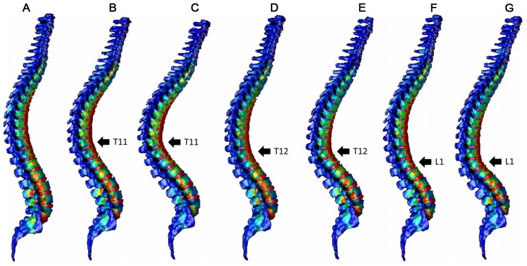
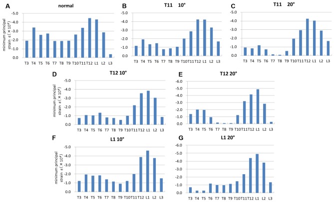
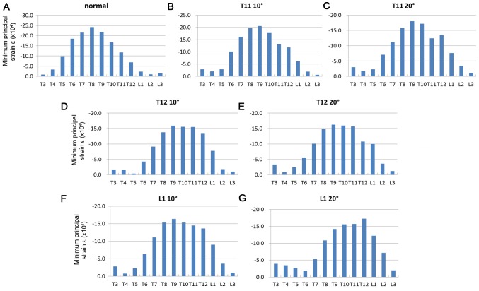
Vertebral fractures commonly occur at the thoracolumbar junction. These fractures can be treated with mild residual deformity in many cases, but are reportedly associated with increased risk of secondary vertebral fractures. In the present study, a three-dimensional (3D) whole spine model was constructed using the finite element method to explore the mechanism of development of compression fractures. The 3D model of the whole spine, from the cervical spine to the pelvis, was constructed from computed tomography (CT) images of an adult male. Using a normal spine model and spine models with compression fractures at the T11, T12 or L1 vertebrae, the distribution of strain was analyzed in the vertebrae after load application. The normal spine model demonstrated greater strain around the thoracolumbar junction and the middle thoracic spine, while the compression fracture models indicated focused strain at the fracture site and adjacent vertebrae. Increased load time resulted in the extension of the strain region up to the middle thoracic spine. The present findings, that secondary vertebral fractures commonly occur around the fracture site, and may also affect the thoracic vertebrae, are consistent with previous clinical and experimental results. These results suggest that follow-up examinations of compression fractures at the thoracolumbar junction should include the thoracic spine and adjacent vertebrae. The current data also demonstrate that models created from CT images can be used for various analyses.
Keywords: computed tomography; finite element method; secondary vertebral fracture; spinal compression fracture; thoracolumbar junction.
Figures
References
-
- Yoshimura N, Kinoshita H, Oka H, Muraki S, Mabuchi A, Kawaguchi H, Nakamura K. Cumulative incidence and changes in the prevalence of vertebral fractures in a rural Japanese community: A 10-year follow-up of the Miyama cohort. Arch Osteoporos. 2006;1:43–49. doi: 10.1007/s11657-006-0007-0. - DOI
-
- Yoshimura N, Muraki S, Oka H, Mabuchi A, En-Yo Y, Yoshida M, Saika A, Yoshida H, Suzuki T, Yamamoto S, et al. Prevalence of knee osteoarthritis, lumbar spondylosis, and osteoporosis in Japanese men and women: The research on osteoarthritis/osteoporosis against disability study. J Bone Miner Metab. 2009;27:620–628. doi: 10.1007/s00774-009-0080-8. - DOI - PubMed
-
- Ismail AA, Cooper C, Felsenberg D, Varlow J, Kanis JA, Silman AJ, O'Neill TW. Number and type of vertebral deformities: Epidemiological characteristics and relation to back pain and height loss. European vertebral osteoporosis study group. Osteoporos Int. 1999;9:206–213. doi: 10.1007/s001980050138. - DOI - PubMed
LinkOut - more resources
Full Text Sources
Other Literature Sources