Review
. 2018 Mar 22;18(4):948.
doi: 10.3390/s18040948.

Recent Progress in Technologies for Tactile Sensors

Affiliations
Review

Recent Progress in Technologies for Tactile Sensors

Cheng Chi et al. Sensors (Basel). .

Abstract

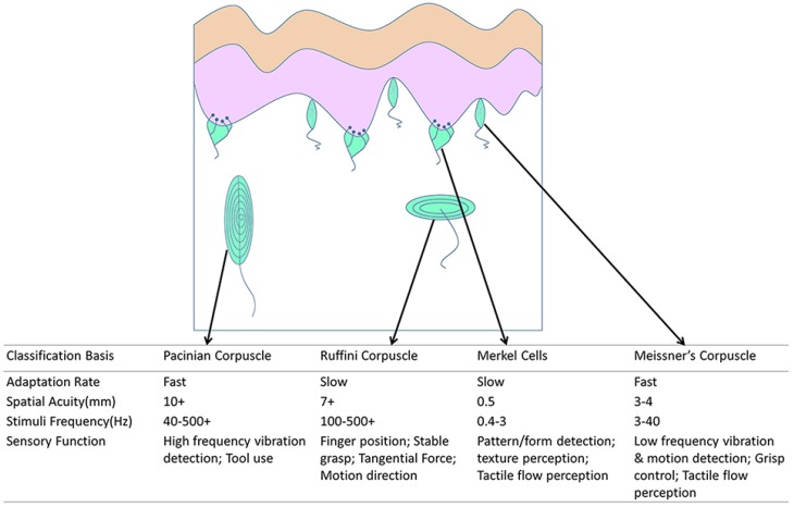
Over the last two decades, considerable scientific and technological efforts have been devoted to developing tactile sensing based on a variety of transducing mechanisms, with prospective applications in many fields such as human-machine interaction, intelligent robot tactile control and feedback, and tactile sensorized minimally invasive surgery. This paper starts with an introduction of human tactile systems, followed by a presentation of the basic demands of tactile sensors. State-of-the-art tactile sensors are reviewed in terms of their diverse sensing mechanisms, design consideration, and material selection. Subsequently, typical performances of the sensors, along with their advantages and disadvantages, are compared and analyzed. Two major potential applications of tactile sensing systems are discussed in detail. Lastly, we propose prospective research directions and market trends of tactile sensing systems.

Keywords: MIS; humanoid robot; tactile sensor; technologies progress review.


Conflict of interest statement

The authors declare no conflict of interest.

Figures

Figure 1
Figure 1
Illustration of the distribution and classification of various mechanoreceptors [10,13,14,15,16,17,18].
Figure 2
Figure 2
Flexible pressure-sensitive organic thin film transistors (OTFTs). (a) Schematic of the fabrication step; (bd) electric characteristics of the OTFTs. Reprinted from [86], copyright (2013), with permission from Nature Publishing Group.
Figure 3
Figure 3
(a) Schematic diagram of the capacitive tactile sensing array; (b) cross-section view of one sensing unit; (c) schematic diagram of different geometries of the microstructures on the polydimethylsiloxane (PDMS) layer. Reprint from [89], copyright (2016), with permission from MDPI AG.
Figure 4
Figure 4
Tactile sensor array with a truncated PDMS pyramid array as a dielectric layer. (a) Schematic view of the capacitive tactile sensor unit; (b) top view of the capacitive tactile sensor unit; (c) cross-section view along M–M’ © [2015] IEEE. Reprinted, with permission, from [62].
Figure 5
Figure 5
Flexible polymer-based three-axial force sensor. (a,b) A conceptual view of the sensor; (c) sensor and condition circuit; (d,e) the sensor conforming to a pen and fingertip. Reprinted from [59], copyright (2012), with permission from IOP Publishing.
Figure 6
Figure 6
(a) Cross-section view of a sensing cell; (b) illustration of the electrodes in the top view; (c) the sensing principle of three-axis force. © [2012] IEEE. Reprinted, with permission, from [93].
Figure 7
Figure 7
Illustration of ultrasonication process to fabricate polymer/carbon-nanotube (CNT) composites.
Figure 8
Figure 8
(a) Illustration of flatbed screen printing; (b) an illustration of rotary screen printing © [2015] IEEE. Reprinted, with permission, from [118].
Figure 9
Figure 9
Schematic view of strain gauge.
Figure 10
Figure 10
(a) Schematic view of the proposed tactile senor with three kinds of convex microstructure; (b) schematic view of the sensing mechanism; (c) experimental results of the proposed tactile sensor. Reprint from [127], copyright (2014), with permission from Elsevier.
Figure 11
Figure 11
(a) Schematic view of the tactile sensor; (b) a schematic view of the bridge circuit to measure shear force. Reprint from [128], copyright (2013), with permission from Elsevier.
Figure 12
Figure 12
Working principle of a conventional capacitive tactile sensor and the magnetic tactile sensor © [2013] IEEE. Reprinted, with permission, from [130].
Figure 13
Figure 13
(ae) Fabrication process of the tactile sensor. (f) Microscope image of the GMR sensor array prior to cilia integration. (g) Optical image of the fabricated sensors. (h) SEM image of a cilia array. Each cilium is 1 mm in length and 200 μm in diameter © [2016] IEEE. Reprinted, with permission, from [131].
Figure 14
Figure 14
Structure and conformation of the proposed three-dimensional tactile sensor © [2012] IEEE. Reprinted, with permission, from [76].
Figure 15
Figure 15
Working principle diagram of the three-dimensional tactile sensor: (a) without load; (b) under compression; (c) under a shear force © [2012] IEEE. Reprinted, with permission, from [76].
Figure 16
Figure 16
(ac)The optical photographs of the fabricated dome-shaped polyvinylidene fluoride (PVDF) film and tactile sensors. Reprinted from [134], copyright (2014), with permission from Elsevier.
Figure 17
Figure 17
(a) Structure view of the proposed tactile sensor. (b) Image of the miniaturized tactile sensor (Ø = 1.5 mm) mounted on an endoscope. Reprinted from [135] copyright (2016), with permission from Elsevier.
Figure 18
Figure 18
(a) Design of tactile sensor with mirror placement. (b) Video output with unload status. (c) Video output with force applied in central element © [2012] IEEE. Reprinted, with permission, from [72].
Figure 19
Figure 19
Spectra of FBGs reflecting light under strain or compression. (a) Without strain or compression; (b) the reflected wavelength is shifted to higher wavelengths under strain; (c) the reflected wavelength is shifted to lower wavelengths under compression © [2012] IEEE. Reprinted, with permission, from [138].
Figure 20
Figure 20
Three major components of the da Vinci Surgical System: (a) vision system; (b) surgeon console; (c) patient-side cart. Reprinted from [153].
Figure 21
Figure 21
(a) The manipulation of HeroSurg; (b) the workstation console of HeroSurg. Reprinted from [161].

Similar articles

Cited by

References

    1. Wang X., Dong L., Zhang H., Yu R., Pan C., Wang Z.L. Recent Progress in Electronic Skin. Adv. Sci. 2015;2 doi: 10.1002/advs.201500169. - DOI - PMC - PubMed
    1. Girão P.S., Ramos P.M.P., Postolache O., Pereira J.M.D. Tactile sensors for robotic applications. Measurement. 2013;46:1257–1271. doi: 10.1016/j.measurement.2012.11.015. - DOI
    1. Hu X., Zhang X., Liu M., Chen Y., Li P., Pei W., Zhang C., Chen H. A flexible capacitive tactile sensor array with micro structure for robotic application. Sci. China Inf. Sci. 2014;57:1–6. doi: 10.1007/s11432-014-5191-8. - DOI
    1. Fritzsche M., Elkmann N., Schulenburg E. Tactile sensing: A key technology for safe physical human robot interaction; Proceedings of the 6th International Conference on Human-Robot Interaction; Lausanne, Switzerland. 6–9 March 2011; pp. 139–140.
    1. Johansson R.S., Westling G. Roles of glabrous skin receptors and sensorimotor memory in automatic control of precision grip when lifting rougher or more slippery objects. Exp. Brain Res. 1984;56:550–564. doi: 10.1007/BF00237997. - DOI - PubMed

LinkOut - more resources