

Near-Infrared-Emitting CuInS2/ZnS Dot-in-Rod Colloidal Heteronanorods by Seeded Growth
- PMID: 29569443
- PMCID: PMC5934729
- DOI: 10.1021/jacs.8b01412
Near-Infrared-Emitting CuInS2/ZnS Dot-in-Rod Colloidal Heteronanorods by Seeded Growth
Abstract
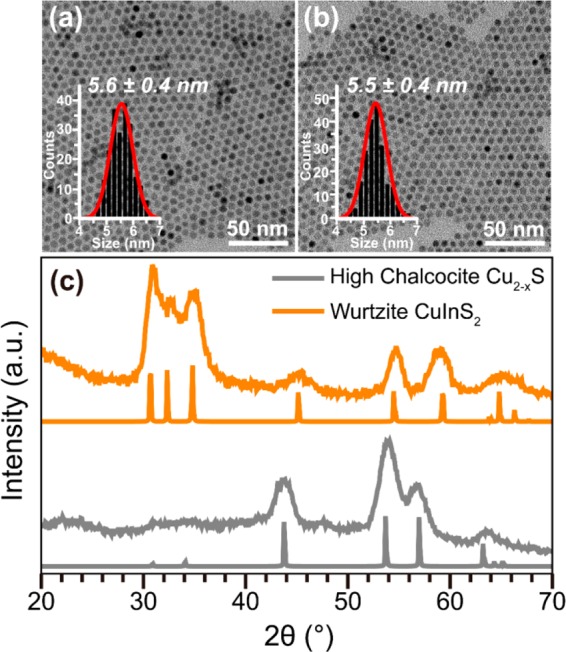
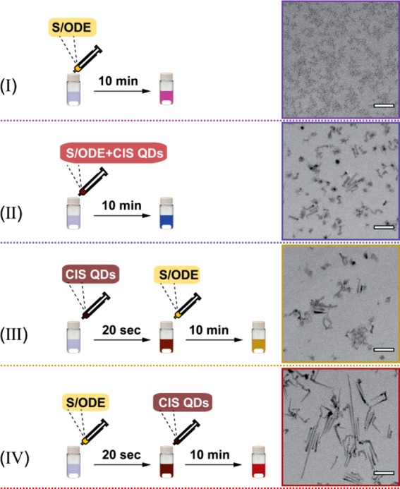
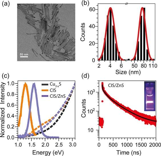
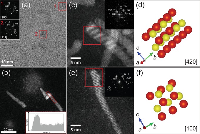
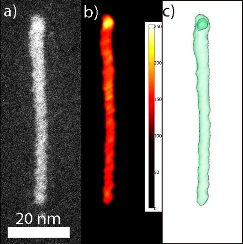
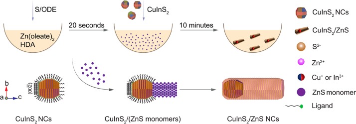
Synthesis protocols for anisotropic CuInX2 (X = S, Se, Te)-based heteronanocrystals (HNCs) are scarce due to the difficulty in balancing the reactivities of multiple precursors and the high solid-state diffusion rates of the cations involved in the CuInX2 lattice. In this work, we report a multistep seeded growth synthesis protocol that yields colloidal wurtzite CuInS2/ZnS dot core/rod shell HNCs with photoluminescence in the NIR (∼800 nm). The wurtzite CuInS2 NCs used as seeds are obtained by topotactic partial Cu+ for In3+ cation exchange in template Cu2- xS NCs. The seed NCs are injected in a hot solution of zinc oleate and hexadecylamine in octadecene, 20 s after the injection of sulfur in octadecene. This results in heteroepitaxial growth of wurtzite ZnS primarily on the Sulfur-terminated polar facet of the CuInS2 seed NCs, the other facets being overcoated only by a thin (∼1 monolayer) shell. The fast (∼21 nm/min) asymmetric axial growth of the nanorod proceeds by addition of [ZnS] monomer units, so that the polarity of the terminal (002) facet is preserved throughout the growth. The delayed injection of the CuInS2 seed NCs is crucial to allow the concentration of [ZnS] monomers to build up, thereby maximizing the anisotropic heteroepitaxial growth rates while minimizing the rates of competing processes (etching, cation exchange, alloying). Nevertheless, a mild etching still occurred, likely prior to the onset of heteroepitaxial overgrowth, shrinking the core size from 5.5 to ∼4 nm. The insights provided by this work open up new possibilities in designing multifunctional Cu-chalcogenide based colloidal heteronanocrystals.
Conflict of interest statement
The authors declare no competing financial interest.
Figures
Similar articles
-
Synthesis and Formation Mechanism of Colloidal Janus-Type Cu2-xS/CuInS2 Heteronanorods via Seeded Injection.ACS Nano. 2021 Jun 22;15(6):9987-9999. doi: 10.1021/acsnano.1c01488. Epub 2021 Jun 10. ACS Nano. 2021. PMID: 34110780 Free PMC article.
-
Seeded Growth Combined with Cation Exchange for the Synthesis of Anisotropic Cu2-x S/ZnS, Cu2-x S, and CuInS2 Nanorods.Chem Mater. 2021 Jan 12;33(1):102-116. doi: 10.1021/acs.chemmater.0c02817. Epub 2020 Dec 28. Chem Mater. 2021. PMID: 33456135 Free PMC article.
-
Near-Infrared Emitting CuInSe₂/CuInS₂ Dot Core/Rod Shell Heteronanorods by Sequential Cation Exchange.ACS Nano. 2015 Nov 24;9(11):11430-8. doi: 10.1021/acsnano.5b05496. Epub 2015 Oct 12. ACS Nano. 2015. PMID: 26449673 Free PMC article.
-
Prospects of Colloidal Copper Chalcogenide Nanocrystals.Chemphyschem. 2016 Mar 3;17(5):559-81. doi: 10.1002/cphc.201500976. Epub 2016 Feb 2. Chemphyschem. 2016. PMID: 26684665 Review.
-
Synthesis and hybridization of CuInS2 nanocrystals for emerging applications.Chem Soc Rev. 2023 Nov 27;52(23):8374-8409. doi: 10.1039/d3cs00611e. Chem Soc Rev. 2023. PMID: 37947021 Review.
Cited by
-
Interplay between Surface Chemistry, Precursor Reactivity, and Temperature Determines Outcome of ZnS Shelling Reactions on CuInS2 Nanocrystals.Chem Mater. 2018 Apr 10;30(7):2400-2413. doi: 10.1021/acs.chemmater.8b00477. Epub 2018 Mar 25. Chem Mater. 2018. PMID: 29657360 Free PMC article.
-
Environmentally friendly synthesis of quantum dots and their applications in diverse fields from the perspective of environmental compliance: A review.Discov Nano. 2025 Aug 8;20(1):132. doi: 10.1186/s11671-025-04323-6. Discov Nano. 2025. PMID: 40779282 Free PMC article. Review.
-
Synthesis and Formation Mechanism of Colloidal Janus-Type Cu2-xS/CuInS2 Heteronanorods via Seeded Injection.ACS Nano. 2021 Jun 22;15(6):9987-9999. doi: 10.1021/acsnano.1c01488. Epub 2021 Jun 10. ACS Nano. 2021. PMID: 34110780 Free PMC article.
-
Seeded Growth Combined with Cation Exchange for the Synthesis of Anisotropic Cu2-x S/ZnS, Cu2-x S, and CuInS2 Nanorods.Chem Mater. 2021 Jan 12;33(1):102-116. doi: 10.1021/acs.chemmater.0c02817. Epub 2020 Dec 28. Chem Mater. 2021. PMID: 33456135 Free PMC article.
-
Photoluminescent, "ice-cream cone" like Cu-In-(Zn)-S/ZnS nanoheterostructures.Sci Rep. 2022 Apr 6;12(1):5787. doi: 10.1038/s41598-022-09646-3. Sci Rep. 2022. PMID: 35388059 Free PMC article.
References
Publication types
LinkOut - more resources
Full Text Sources
Other Literature Sources
Miscellaneous
