. 2018 Mar 29;9(1):1278.
doi: 10.1038/s41467-018-03688-w.

Helraiser intermediates provide insight into the mechanism of eukaryotic replicative transposition

Affiliations

Helraiser intermediates provide insight into the mechanism of eukaryotic replicative transposition

Ivana Grabundzija et al. Nat Commun. .

Abstract

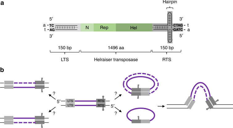
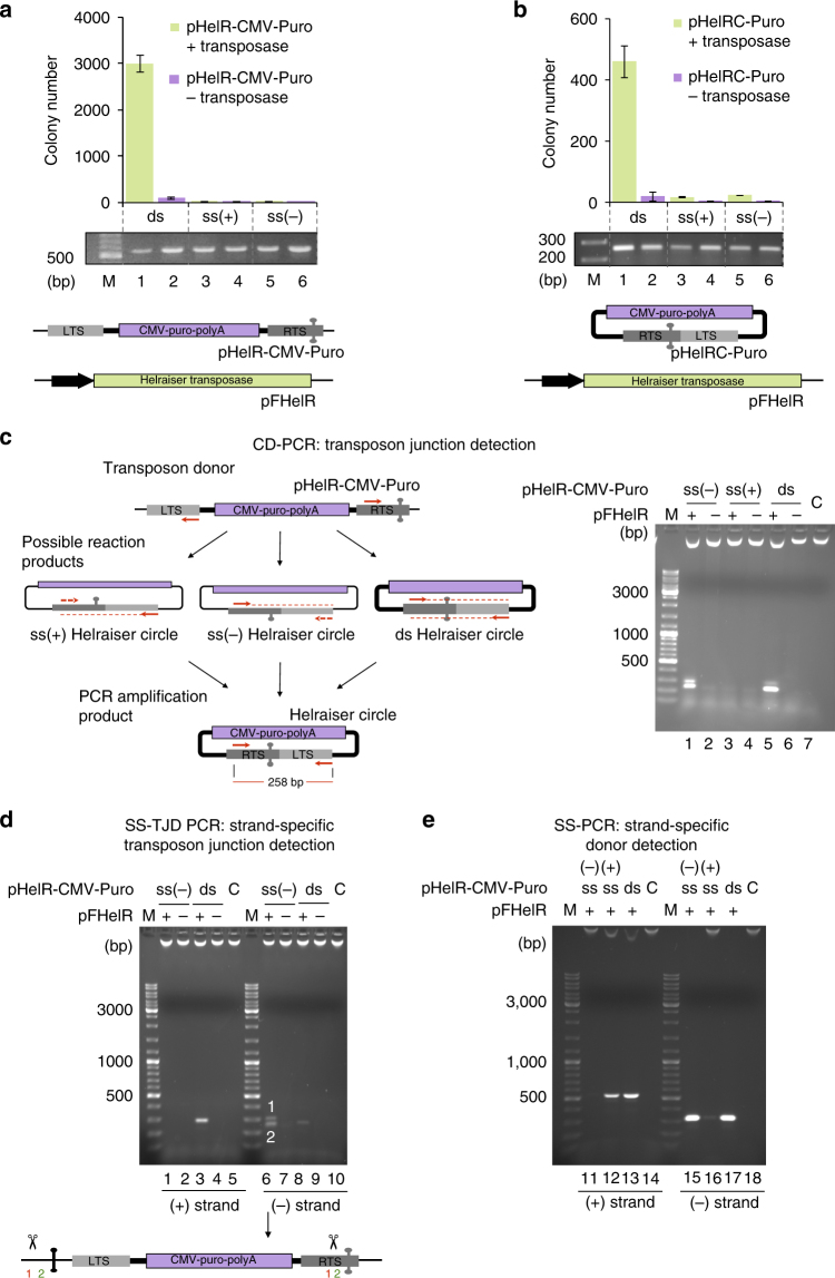
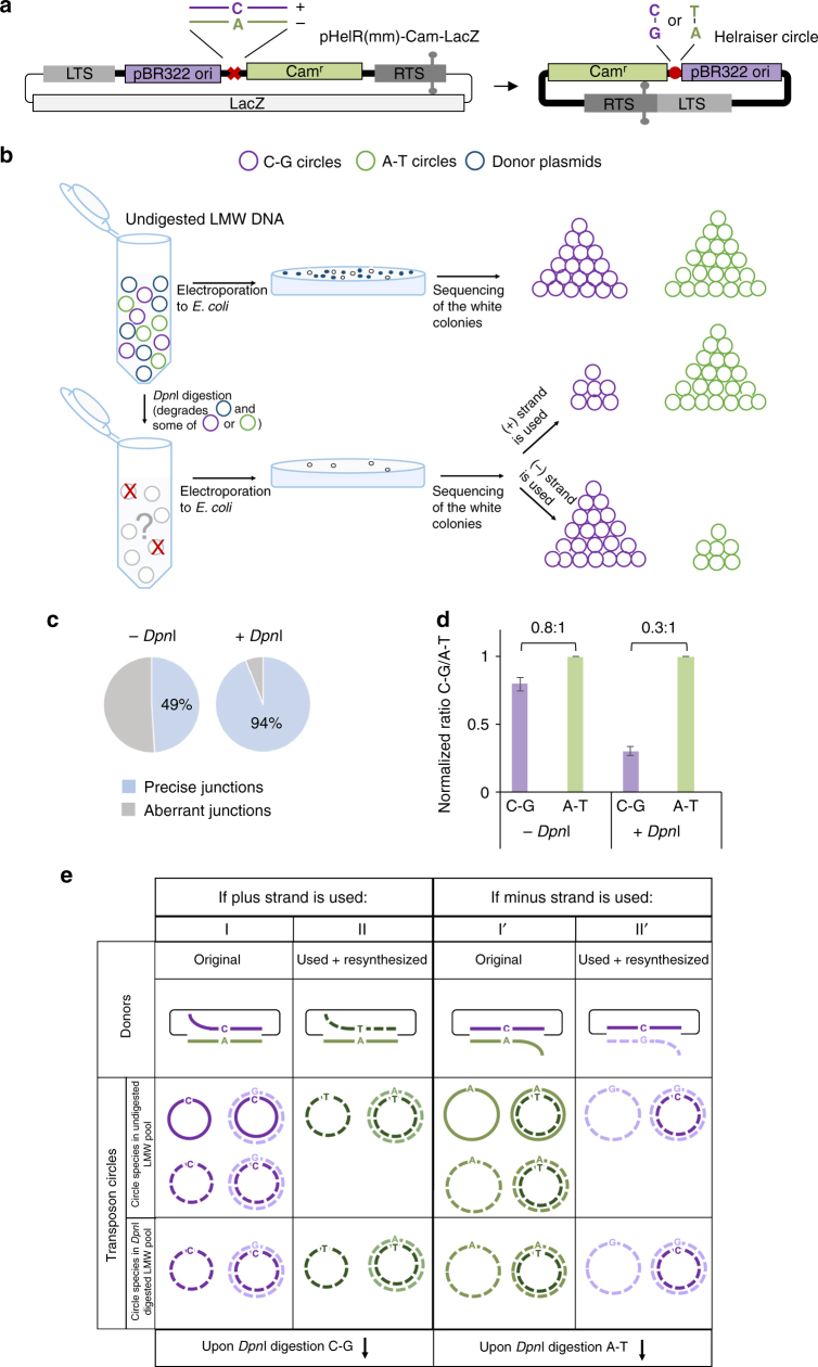
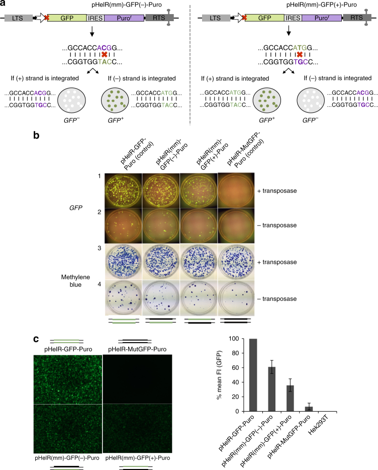
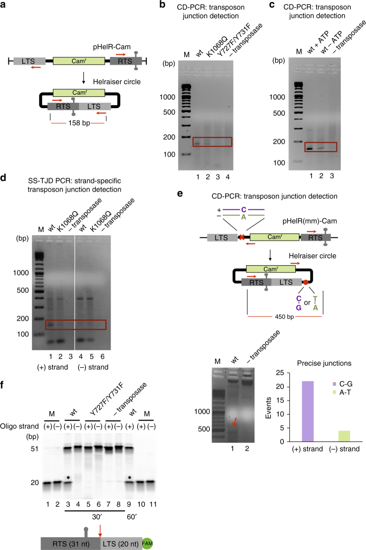
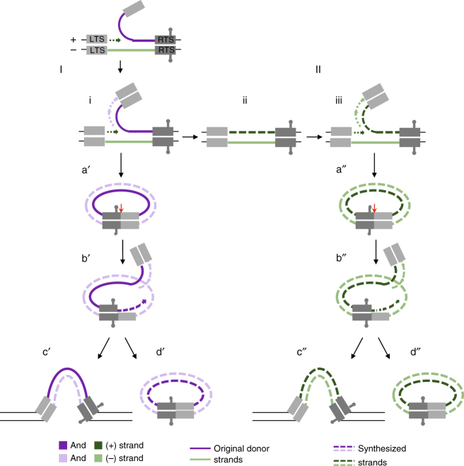
Helitrons are eukaryotic DNA transposons that have profoundly affected genome variability via capture and mobilization of host genomic sequences. Defining their mode of action is therefore important for understanding how genome landscapes evolve. Sequence similarities with certain prokaryotic mobile elements suggest a "rolling circle" mode of transposition, involving only a single transposon strand. Using the reconstituted Helraiser transposon to study Helitron transposition in cells and in vitro, we show that the donor site must be double-stranded and that single-stranded donors will not suffice. Nevertheless, replication and integration assays demonstrate the use of only one of the transposon donor strands. Furthermore, repeated reuse of Helraiser donor sites occurs following DNA synthesis. In cells, circular double-stranded intermediates that serve as transposon donors are generated and replicated by Helraiser transposase. Cell-free experiments demonstrate strand-specific cleavage and strand transfer, supporting observations made in cells.


Conflict of interest statement

The authors declare no competing interests.

Figures

Fig. 1
Fig. 1
Features of Helraiser transposon and overview of transposition pathway. a Schematic representation of Helraiser transposon. The 150-bp left terminal sequence (LTS) is shown in light gray, and the 150-bp right terminal sequence (RTS) in dark gray, with the location of a potential hairpin indicated. N-terminal, Rep and helicase domains of the Helraiser transposase are shown as green rectangles. Conserved di- and tetranucleotide terminal sequence motifs are in uppercase. Flanking host A-T dinucleotide is in lowercase. b Schematic model and open questions of Helitron transposition. The transposase is proposed to excise one of the transposon strands from the double-stranded donor molecule (shown in the middle). Transposon excision is most likely followed by DNA synthesis that regenerates the transposon donor site (shown on the left). The excised transposon strand forms a single or double-stranded transposon circle that is possibly integrated into the target site in the host genome (shown on the right). LTS is shown in light gray and the RTS in dark gray. Solid purple lines: transposon donor strands; black lines: genomic sequence; and dashed lines: synthesized transposon strands
Fig. 2
Fig. 2
Helraiser transposition from single- and double-stranded donors in human HEK cells. a Top: Helraiser transposition efficiency from double-stranded (ds) and single-stranded (ss) transposon donors, measured by Puro-resistant colony formation in HEK293T cells. All data are presented as a mean ± s.e.m., n = 3 biological replicates. M marker, ds transfected ds donors, ss(+) transfected plus-strand ss donors, ss(−) transfected minus-strand ss donors. Middle: PCR detection of transfected ds and ss transposon donors. All PCRs are performed with low-molecular weight (LMW) DNA isolated 48 h post-transfection. Bottom: schematic of the relevant portions of Helraiser donor (pHelR-CMV-Puro) and helper (pFHelR) plasmids. All plasmids are used in closed, circular form unless otherwise stated. Uncropped gel image is provided in Supplemental Fig. 1a. b Top: Helraiser transposition efficiency from ds, ss(+), and ss(−) transposon circles, as measured by Puro-resistant colony formation in HEK293 cells. ds transfected ds transposon circles, ss(+) transfected plus-strand ss transposon circles, ss(−) transfected minus-strand ss transposon circles. Middle: PCR detection of transfected ds and ss transposon circles. Bottom: schematic of the Helraiser circle (pHelRC-Puro) and helper (pFHelR) plasmid. Uncropped gel image is provided in Supplemental Fig. 1a. c Helraiser junction formation from ds and ss transposon donors. Left: outline of the CD-PCR method. Red arrows: forward (fwd) and reverse (rev) primer binding sites; dashed red line: first PCR cycle amplification products; dashed red arrows: primer binding sites on amplified products; full red line: final ds amplification product. Right: junction detection by CD-PCR. C no template control. Co-transfection of transposon donors with transposase helper plasmids is indicated as pFHelR “ + .” pFHelR “−” indicates co-transfection with control plasmids. d SS-TJD PCR of transposon circles. Lanes 1–5: PCR detects plus strand. Lanes 6–10: PCR detects minus strand. In lane 6, two sequenced PCR products containing Helraiser end junctions are indicated. Bottom: positions of the aberrant cleavage sites on the transposon donor molecule prior to end joining are indicated. e SS-PCR of transposon donors. Lanes 11–13, PCR detects plus strand; lanes 15–17, PCR detects minus strand
Fig. 3
Fig. 3
Helraiser circle replication and donor site repair in HEK293T cells. a Schematic of the Helraiser heteroduplex LacZ donor plasmid (pHelR(mm)-Cam-LacZ) and resulting Helraiser circle. The red cross indicates the mismatch position within the transposon sequence, and the red circle marks the position of the mismatch used in the analysis of the Helraiser circles. b Experimental design of transposon circle replication assay using heteroduplex pHelR(mm)-Cam-LacZ donor plasmid. As shown, DpnI digestion of LMW DNA reaction products can be used to distinguish between transposition of the (+) strand and the (−) strand. c Proportion of the transposon circles containing precise LTS-to-RTS junctions before and after DpnI digestion of electroporated LMW DNA. The data are presented as n = 3 biological replicates. d Results of the transposon circle replication assay with pHelR(mm)-Cam-LacZ plasmid. The data are presented as a mean ± s.e.m., n = 3 biological replicates. e Schematic representation of possible outcomes of the transposon circle replication assay with heteroduplex pHelR(mm)-Cam-LacZ donors. Purple line: (+) strand of transposon donor; green line: (−) strand of transposon donor; solid line: methylated DNA; dashed line: unmethylated DNA; thin black line: plasmid backbone
Fig. 4
Fig. 4
Helraiser transposition from heteroduplex GFP-Puro reporter plasmids in HEK293T cells. a Schematic of relevant portions of Helraiser heteroduplex GFP-Puro donor plasmids, pHelR(mm)-GFP(−)-Puro (left) and pHelR(mm)-GFP(+)-Puro (right). Shown are possible outcomes of Helraiser transposon integration for each of the two heteroduplex donors. Mismatch positions on transposon donors are indicated by red x with sequences shown below. Mutated sequence of the GFP start codon is in purple; intact GFP start codon in green. Schematic representations of tissue culture plates with GFP negative (GFP−) and GFP positive (GFP+) Puro-resistant colonies are as shown. b Colony-forming assay with the two heteroduplex and the two control transposon donors. Tissue culture plates containing Puro-resistant colonies 22 days post-transfection were first imaged under blue light (GFP) followed by methylene blue staining. c FACS analysis of the GFP fluorescence intensity (FI) in Puro-resistant Hek293T cells 22 days post-transfection. Left: fluorescence microscopy images show the Puro-resistant cell suspensions used for FACS analysis. The data are presented as a mean ± s.e.m., n = 3 biological replicates. Schematic of transposon donors indicate the transposon strand with mutated (thick black line) and the intact GFP start codon (thick green line); thin black lines: plasmid backbone
Fig. 5
Fig. 5
In vitro transposon-end junction formation and cleavage with purified Helraiser transposase. a Helraiser donor plasmid (pHelR-Cam), used in linear form, and resulting Helraiser circle. Red arrows represent fwd and rev nested primer binding sites; red line: expected size of the PCR product. b PCR detection of Helraiser transposon-end junctions. M marker, Red box marks the position of the expected PCR product. c PCR detection of Helraiser transposon-end junctions ±ATP. d Strand-specific PCR detection of transposon-end junctions generated in vitro by the Helraiser transposase. Lanes 1–3: detection of plus strand. Lanes 4–6: detection of minus strand. e Top: schematic of Helraiser heteroduplex donor plasmid, pHelR(mm)-Cam and resulting Helraiser circle. Red x mismatch position within transposon sequence; red circle position of the mismatch on the donor molecule used in the analysis of the Helraiser circles. Bottom left: PCR detection of the transposon-end junctions generated from the heteroduplex donor. Red arrow indicates PCR product of the expected size spanning the mismatch position. Bottom right: DNA base composition at the mismatch position in the obtained PCR product. Most of the detected junctions arose from the plus strand; four arose from the minus strand. f Top: cleavage of ss 51-mer DNA oligonucleotides representing plus and minus strand of transposon-end junction. Marker (M): 20 bp oligonucleotide corresponding to the expected cleavage product for each strand. Bottom: schematic representation of the ss oligonucleotide used in cleavage reactions. Red arrow indicates the cleavage site. Oligonucleotide sequences are listed in Supplementary table 1
Fig. 6
Fig. 6
Proposed pathways of transposon circle formation together with replication and integration during Helraiser transposition. Transposon circle formation using the original donor site is shown on the left (I). Following the nicking of transposon plus strand at the LTS, a replication fork is established at the nick site (i). Leading strand synthesis reconstitutes the transposon donor site (ii), while lagging strand synthesis takes place on the displaced transposon strand. This results in a formation of dsDNA transposon circle (a′) after the second cleavage reaction takes place at the RTS of the displaced transposon strand. Generated dsDNA transposon circle potentially serves as a transposon donor (b′). Following the transposon plus-strand cleavage at the LTS-to-RTS junction site on a dsDNA transposon circle, a replication fork is established at the nick site (b′). Leading strand synthesis regenerates the transposon donor site on the transposon circle, while the lagging strand synthesis results in a dsDNA transposon copy that can be integrated in the host genome (c′) or form a new dsDNA transposon circle (d′). After resynthesis of the original transposon donor site (shown on the right (II)), transposon circle formation and replication include the same steps illustrated for the pathway (I). Solid line: original transposon donor strand; dashed line: synthesized transposon strand. Transposon plus strand is shown in dark purple or in dark green; transposon minus strand is shown in light purple or in light green. Red arrow marks the position of the transposon plus-strand cleavage at the LTS-to-RTS junction site

Similar articles

Cited by

References

    1. Agrawal A, Eastman QM, Schatz DG. Transposition mediated by RAG1 and RAG2 and its implications for the evolution of the immune system. Nature. 1998;394:744–751. doi: 10.1038/29457. - DOI - PubMed
    1. Kapitonov VV, Jurka J. RAG1 core and V(D)J recombination signal sequences were derived from Transib transposons. PLoS Biol. 2005;3:e181. doi: 10.1371/journal.pbio.0030181. - DOI - PMC - PubMed
    1. Mi S, et al. Syncytin is a captive retroviral envelope protein involved in human placental morphogenesis. Nature. 2000;403:785–789. doi: 10.1038/35001608. - DOI - PubMed
    1. Ono R, et al. Deletion of Peg10, an imprinted gene acquired from a retrotransposon, causes early embryonic lethality. Nat. Genet. 2006;38:101–106. doi: 10.1038/ng1699. - DOI - PubMed
    1. Feschotte C. Transposable elements and the evolution of regulatory networks. Nat. Rev. Genet. 2008;9:397–405. doi: 10.1038/nrg2337. - DOI - PMC - PubMed

Publication types