

Chromatic induction in space and time
- PMID: 29603978
- PMCID: PMC6022834
- DOI: 10.1364/JOSAA.35.00B223
Chromatic induction in space and time
Abstract
The color appearance of a light depends on variation in the complete visual field over both space and time. In the spatial domain, a chromatic stimulus within a patterned chromatic surround can appear a different hue than the same stimulus within a uniform surround. In the temporal domain, a stimulus presented as an element of a continuously changing chromaticity can appear a different color compared to the identical stimulus, presented simultaneously but viewed alone. This is the flash-lag effect for color, which has an analog in the domain of motion: a pulsed object seen alone can appear to lag behind an identical pulsed object that is an element of a motion sequence. Studies of the flash-lag effect for motion have considered whether it is mediated by a neural representation for the moving physical stimulus or, alternatively, for the perceived motion. The current study addresses this question for the flash-lag effect for color by testing whether the color flash lag depends on a representation of only the changing chromatic stimulus or, alternatively, its color percept, which can be altered by chromatic induction.
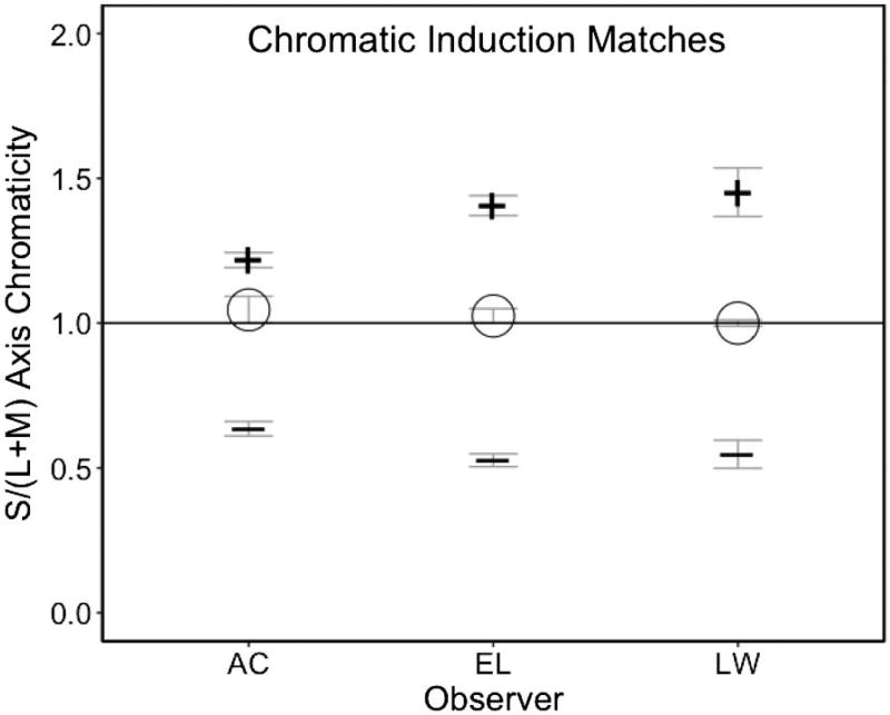
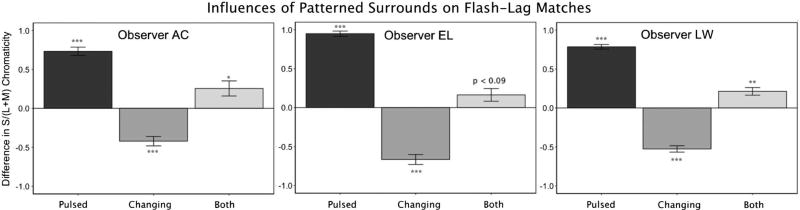
Methods: baseline measurements for spatial chromatic induction determined the chromaticity of a flashed ring within a uniform surround that matched a flashed ring within a patterned surround. Baseline measurements for the color flash-lag effect determined the chromaticity of a pulsed ring presented alone (within a uniform surround) that matched a pulsed ring presented in a sequence of changing chromaticity over time (also within a uniform surround). Finally, the main experiments combined chromatic induction from a patterned surround and the flash-lag effect, in three conditions: (1) both the changing and pulsed rings were within a patterned chromatic surround; (2) the changing ring was within a patterned surround and the pulsed ring within a uniform surround; and (3) the changing ring was within a uniform surround and the pulsed ring within a patterned surround.
Results: the flash-lag measurements for a changing chromaticity were affected by perceptual changes induced by the surrounding chromatic pattern. Thus, the color shifts induced by a chromatic surround are incorporated in the neural representation mediating the flash-lag effect for color.
Figures


Similar articles
-
Chromatic induction from surrounding stimuli under perceptual suppression.Vis Neurosci. 2014 Nov;31(6):387-400. doi: 10.1017/S0952523814000224. Epub 2014 Aug 19. Vis Neurosci. 2014. PMID: 25136894
-
Stimulus size dependence of hue changes induced by chromatic surrounds.J Opt Soc Am A Opt Image Sci Vis. 2016 Mar;33(3):A267-72. doi: 10.1364/JOSAA.33.00A267. J Opt Soc Am A Opt Image Sci Vis. 2016. PMID: 26974933
-
Standard definitions of chromatic induction fail to describe induction with S-cone patterned backgrounds.Vision Res. 2008 Dec;48(27):2708-14. doi: 10.1016/j.visres.2008.09.011. Epub 2008 Oct 19. Vision Res. 2008. PMID: 18838085
-
The flash-lag effect and related mislocalizations: findings, properties, and theories.Psychol Bull. 2014 Jan;140(1):308-38. doi: 10.1037/a0032899. Epub 2013 Jun 24. Psychol Bull. 2014. PMID: 23796268 Review.
-
Postdiction: its implications on visual awareness, hindsight, and sense of agency.Front Psychol. 2014 Mar 31;5:196. doi: 10.3389/fpsyg.2014.00196. eCollection 2014. Front Psychol. 2014. PMID: 24744739 Free PMC article. Review.
References
-
- Cao D, Shevell SK. Chromatic assimilation: spread light or neural mechanism? Vis. Res. 2005;45:1031–1045. - PubMed
-
- Evans RM. Introduction to Color. Wiley; 1948.
-
- Jameson D, Hurvich LM. Opponent chromatic induction: experimental evaluation and theoretical account. J. Opt. Soc. Am. 1961;51:46–53. - PubMed
-
- Fach C, Sharpe LT. Assimilative hue shifts in color depend on bar width. Attention Percept. Psychophys. 1986;40:412–418. - PubMed
-
- Helson H. Studies of anomalous contrast and assimilation. J. Opt. Soc. Am. 1963;53:179–184. - PubMed
Grants and funding
LinkOut - more resources
Full Text Sources
Other Literature Sources
