

Wide-Baseline Stereo-Based Obstacle Mapping for Unmanned Surface Vehicles
- PMID: 29617293
- PMCID: PMC5948499
- DOI: 10.3390/s18041085
Wide-Baseline Stereo-Based Obstacle Mapping for Unmanned Surface Vehicles
Abstract
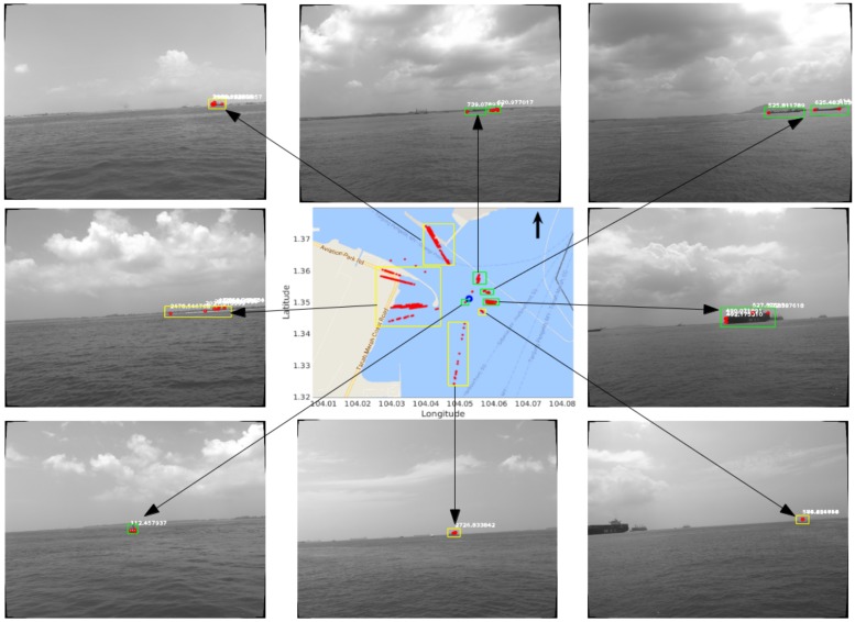
This paper proposes a wide-baseline stereo-based static obstacle mapping approach for unmanned surface vehicles (USVs). The proposed approach eliminates the complicated calibration work and the bulky rig in our previous binocular stereo system, and raises the ranging ability from 500 to 1000 m with a even larger baseline obtained from the motion of USVs. Integrating a monocular camera with GPS and compass information in this proposed system, the world locations of the detected static obstacles are reconstructed while the USV is traveling, and an obstacle map is then built. To achieve more accurate and robust performance, multiple pairs of frames are leveraged to synthesize the final reconstruction results in a weighting model. Experimental results based on our own dataset demonstrate the high efficiency of our system. To the best of our knowledge, we are the first to address the task of wide-baseline stereo-based obstacle mapping in a maritime environment.
Keywords: obstacle mapping; unmanned surface vehicle; visual odometry; wide-baseline stereo.
Conflict of interest statement
The authors declare no conflict of interest.
Figures


References
-
- Wang H., Mou W., Mou X., Yuan S., Ulun S., Yang S., Shin B. An Automatic Self-calibration Approach for Wide Baseline Stereo Cameras Using Sea Surface Images. Unmanned Syst. 2015;3:277–290. doi: 10.1142/S230138501540004X. - DOI
-
- Wang H., Mou X., Mou W., Yuan S., Ulun S., Yang S., Shin B. Vision Based Long Range Object Detection and Tracking for Unmanned Surface Vehicle; Proceedings of the 2015 IEEE 7th International Conference on Cybernetics and Intelligent Systems (CIS) and IEEE Conference on Robotics, Automation and Mechatronics (RAM); Siem Reap, Cambodia. 15–17 July 2015; pp. 101–105.
-
- Mou X., Wang H., Lim K. Scale-Adaptive Multiple-Obstacle Tracking with Occlusion Handling in Maritime Scenes; Proceedings of the 2016 12th IEEE International Conference on Control and Automation (ICCA); Kathmandu, Nepal. 1–3 June 2016; pp. 588–592.
-
- Shin B., Mou X., Mou W., Wang H. Vision-Based Navigation of An Unmanned Surface Vehicle with Object Detection and Tracking Abilities. Mach. Vis. Appl. 2018;29:95–112. doi: 10.1007/s00138-017-0878-7. - DOI
-
- Mur-Artal R., Montiel J.M.M., Tardos J.D. ORB-SLAM: A Versatile and Accurate Monocular SLAM System. IEEE Trans. Robot. 2015;31:1147–1163. doi: 10.1109/TRO.2015.2463671. - DOI
LinkOut - more resources
Full Text Sources
Other Literature Sources
