. 2018 Apr 5;13(4):e0194890.
doi: 10.1371/journal.pone.0194890. eCollection 2018.

Expert-guided optimization for 3D printing of soft and liquid materials

Affiliations

Expert-guided optimization for 3D printing of soft and liquid materials

Sara Abdollahi et al. PLoS One. .

Abstract

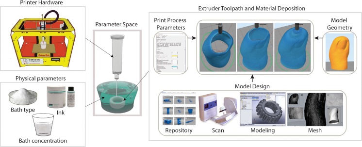
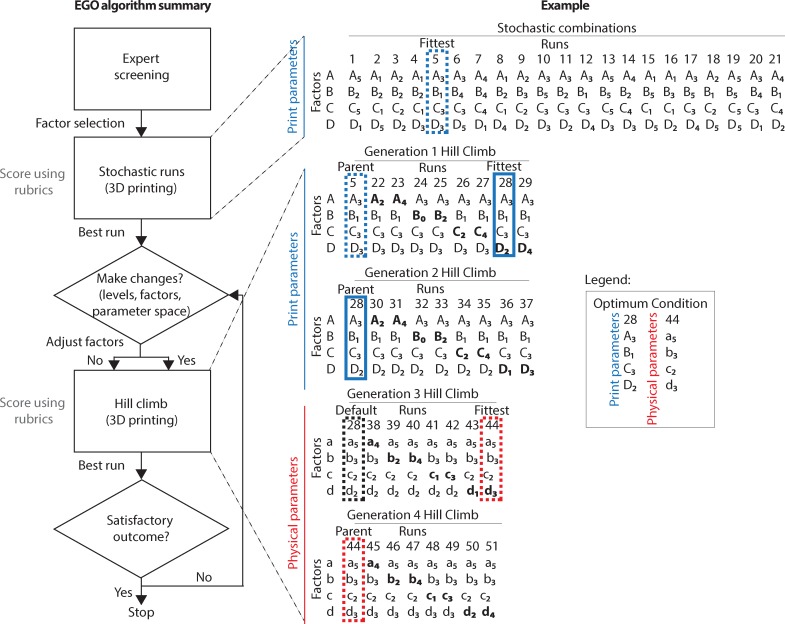
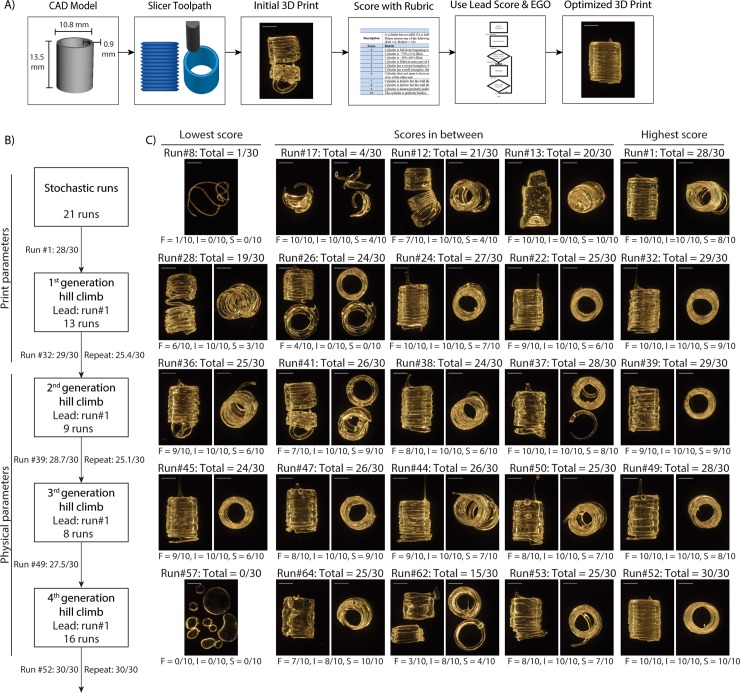
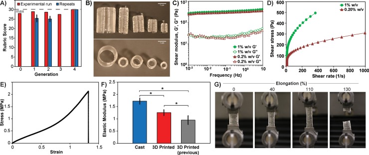
Additive manufacturing (AM) has rapidly emerged as a disruptive technology to build mechanical parts, enabling increased design complexity, low-cost customization and an ever-increasing range of materials. Yet these capabilities have also created an immense challenge in optimizing the large number of process parameters in order achieve a high-performance part. This is especially true for AM of soft, deformable materials and for liquid-like resins that require experimental printing methods. Here, we developed an expert-guided optimization (EGO) strategy to provide structure in exploring and improving the 3D printing of liquid polydimethylsiloxane (PDMS) elastomer resin. EGO uses three steps, starting first with expert screening to select the parameter space, factors, and factor levels. Second is a hill-climbing algorithm to search the parameter space defined by the expert for the best set of parameters. Third is expert decision making to try new factors or a new parameter space to improve on the best current solution. We applied the algorithm to two calibration objects, a hollow cylinder and a five-sided hollow cube that were evaluated based on a multi-factor scoring system. The optimum print settings were then used to print complex PDMS and epoxy 3D objects, including a twisted vase, water drop, toe, and ear, at a level of detail and fidelity previously not obtained.


Conflict of interest statement

Competing Interests: Carnegie Mellon University has filed a patent application on the additive manufacturing of embedded materials technology described herein (Application number: PCT/US2014/048643), and Adam W. Feinberg is an inventor on the patent. This does not alter our adherence to PLOS ONE policies on sharing data and materials.

Figures

Fig 1
Fig 1. Parameter spaces for 3D printing soft materials using FRE.
Five parameter spaces determine the 3D print outcome: physical parameters, printer hardware, model design, model geometry, and print parameters. The model design, model geometry, and print parameters are inputs used by the slicer algorithm to determine the extruder toolpath and material deposition rate. Two of the five parameter spaces (print parameters, physical parameters) are considered throughout the EGO strategy. The printer hardware and model properties (design and geometry) are relatively time intensive to alter quickly and are often preset as design criteria.
Fig 2
Fig 2. The expert-guided optimization (EGO) strategy.
EGO has three steps: (i) Expert screening–identification by the expert of a parameter space (e.g., print parameter space), factors (e.g., A = print speed) and factor levels (e.g., A1 = 5 mm/s, A2 = 10 mm/s, A3 = 15 mm/s, A4 = 25 mm/s, A5 = 30 mm/s) that matter for print optimization. (ii) Hill-climbing algorithm–includes a stochastic stage and a hill climb stage. The stochastic stage consists of 21 prints made by taking random combinations of factors-levels within the selected parameter space. The hill climb stage uses the highest scoring print (fittest) from the stochastic stage as lead run (parent) for iterative adjustments, seeking a stepwise climb toward the optimum. Hill climbs involve adjustments to one factor-level at a time, to a level above and in a subsequent run, to a level below the parent while the other factors are kept constant at the parent value. (iii) Expert decision-making–changes by the expert if the fittest run from the hill climb does not exceed the parent score. The changes can be to the parameter space (e.g., physical parameters) and/or factors (e.g., a = bath concentration) and/or factor levels (e.g., a1 = 0.1 w/v%, A2 = 0.4 w/v%, A3 = 0.5 w/v%, A4 = 1 w/v%, A5 = 2 w/v%). The search stops after reaching a full score. The expert may also choose to terminate the optimization if the search is inconclusive after looping between EGO steps (i) and (ii) in attempts to escape local maxima or if the outcome is satisfactory. In the hypothetical example, the stochastic run is performed for four different print parameters (e.g., A, B, C, and D) followed by two generations of hill climb that end in the fittest factor levels for the print parameter space being from run 28 (A3, B1, C3, D2). These print parameters are then held constant and third and fourth generation hill climb are performed on the physical parameters (e.g., a, b, c, and d), resulting in the fittest factor levels for the physical parameter space from run 44 (a5, b3, c2, d3).
Fig 3
Fig 3. Applying the EGO strategy to 3D printing of calibration cylinders.
(A) Overview of the steps to optimize the cylinder (CAD model) that is imported in to the slicing software to determine the path of the extruder (slicer toolpath). The resulting product (initial 3D print) is assessed (score with rubric) and the fittest run is used as lead in the hill climb (use lead score and EGO) to reach full score (optimized 3D print). (B) Summary of the second step, hill climb, of the EGO strategy for calibration cylinders detailing the total number of runs and the lead run in each within the designated parameter space. (C) Representative images of PDMS 3D prints in each generation with the score for each response variables (layer fusion = F, infill = I, stringiness = S) and the total (lowest, highest, in between). Scale bars are 5 mm.
Fig 4
Fig 4. Characterization of the cylinder optimization conditions and resulting mechanical properties.
(A) Summary of the EGO strategy applied to optimize the cylinder showing the highest score from each generation and the target score of 30. The cylinder optimized after four generations of hill climb. (B) PDMS 3D printed using the EGO optimum scaled-up to five different sizes. The cylinder used throughout the EGO strategy is the second cylinder from the right. Scale bar is 1 cm. (C) Shear modulus as a function of frequency across the 1% w/v (starting) and 0.2% w/v (optimum) Carbopol 940 bath concentrations. The baths are dominantly viscoelastic solids with the storage (G’) modulus larger than the loss modulus (G”). (D) Shear stress versus shear rate at 1% w/v (starting) and 0.2% w/v (optimum) Carbopol 940 bath concentration with a yield stress of 140 Pa and 70 Pa yield stress, respectively. The yield stress is the shear stress at ~4.5 s-1 shear rate (the y-intercept for the linear portion of the shear stress versus shear rate curve). (E) Representative stress-strain curve showing the 3D printed PDMS strip subject to uniaxial tensile tests with the inset displaying the region that is linearly elastic, y = 1.2x + 0.0042 (R2 = 0.996), up to 10% strain. (F) The mean elastic modulus was 1.7 ± 0.1 MPa (SD) for monolithic PDMS (n = 6) made by casting in a previous study [17], 1.2 ± 0.1 MPa (SD) for 3D printed using the EGO found optimum (n = 5), and 0.95 ± 0.2 MPa (SD) for 3D printed (n = 8) in a previous study [6]. Both cast PDMS and 3D printed PDMS have the same base-to-catalyst ratio of 10:1. (G) Representative images of 3D printed PDMS across uniaxial tensile strains up to 130% elongation at break.
Fig 5
Fig 5. Application of the EGO strategy to 3D print calibration cubes.
(A) Dimensions of the cube CAD model, 20 mm × 20 mm × 20 mm, L×W×H, and the resulting S3D slicer toolpath. (B) Summary of the EGO strategy applied to optimize the cube showing the highest score from each generation and the target score of 20. The cube optimized after 12 generations of hill climb. (C) Images of the PDMS 3D print using the Skeinforge CAD slicer to determine toolpath. The print with high bottom score (9/10) had poor wall score (5/10). (D) Images of the PDMS 3D print made using the Skeinforge CAD slicer to determine toolpath. The print with poor bottom score (5/10) had full wall score (10/10), and had the fittest total score (15/20). (E) Images of the PDMS 3D print made using the S3D CAD slicer to determine toolpath. The print with full bottom score (10/10) had poor wall score (5/10), and had the fittest total score (15/20). (F) Images of the PDMS 3D print made using the S3D CAD slicer to determine toolpath. The print with poor bottom score (3/10) had a full wall score (10/10). (G) S3D slicer toolpath of the cube before and after the flip, inverting the build orientation for 3D printing in the support bath, which was achieved at the 12th generation of the cube hill climb. (H) Image of PDMS 3D prints made using the S3D CAD slicer to determine the toolpath. A full total score (20/20) was reached after the flip. Scale bars are 1 cm.
Fig 6
Fig 6. Using the EGO found optimum to 3D print epoxy and PDMS in complex geometries.
(A) The viscosity of both PDMS (~3 Pa·s) and epoxy (~5.3 Pa·s) is constant as a function of shear rate. (B) The linear increase of shear stress as a function of shear rate confirms that before the crosslinking step, both PDMS and epoxy inks are Newtonian fluids. (C) CAD models of the different geometries used for 3D printing with both experimental (PDMS, epoxy) and standard (PLA) materials. (D) Representative image of a twisted vase (15 mm × 33 mm, W×H) 3D prints with standard PLA (left), epoxy (middle), and PDMS (right). (E) Representative image of a water drop vase (17 mm × 52 mm, W×H) 3D prints with standard PLA (left), epoxy (middle), and PDMS (right). (F) Representative image of a life-size toe (25 mm × 44 mm, W×H) 3D prints with standard PLA (left), epoxy (middle), and PDMS (right). (G) Representative image of an ear (20 × 35 mm, W×H) 3D prints with standard PLA (left), epoxy (middle), and PDMS (right). (H) Representative color maps of the water drop vase highlighting the deviation of PLA, epoxy, and PDMS 3D prints from the CAD model. (I) Surface area of the CAD model versus the PLA control, epoxy and PDMS for each 3D printed structure (n = 3) shown in D–G.

References

    1. Wehner M, Truby RL, Fitzgerald DJ, Mosadegh B, Whitesides GM, Lewis JA, et al. An integrated design and fabrication strategy for entirely soft, autonomous robots. Nature. 2016;536(7617):451–5. doi: 10.1038/nature19100 - DOI - PubMed
    1. Lind JU, Busbee TA, Valentine AD, Pasqualini FS, Yuan H, Yadid M, et al. Instrumented cardiac microphysiological devices via multimaterial three-dimensional printing. Nat Mater. 2017;16(3):303–8. doi: 10.1038/nmat4782 - DOI - PMC - PubMed
    1. Hinton TJ, Jallerat Q, Palchesko RN, Park JH, Grodzicki MS, Shue H-J, et al. Three-dimensional printing of complex biological structures by freeform reversible embedding of suspended hydrogels. Science Advances. 2015;1(9). - PMC - PubMed
    1. Mohamed OA, Masood SH, Bhowmik JL. Optimization of fused deposition modeling process parameters: a review of current research and future prospects. Adv Manuf. 2015;3(1):42–53.
    1. Bhattacharjee T, Zehnder SM, Rowe KG, Jain S, Nixon RM, Sawyer WG, et al. Writing in the granular gel medium. Science Advances. 2015;1(8). - PMC - PubMed

Publication types