. 2018 Apr 6;9(1):1334.
doi: 10.1038/s41467-018-03776-x.

Control of laser plasma accelerated electrons for light sources

Affiliations

Control of laser plasma accelerated electrons for light sources

T André et al. Nat Commun. .

Erratum in

  • Publisher Correction: Control of laser plasma accelerated electrons for light sources.
    André T, Andriyash IA, Loulergue A, Labat M, Roussel E, Ghaith A, Khojoyan M, Thaury C, Valléau M, Briquez F, Marteau F, Tavakoli K, N'Gotta P, Dietrich Y, Lambert G, Malka V, Benabderrahmane C, Vétéran J, Chapuis L, El Ajjouri T, Sebdaoui M, Hubert N, Marcouillé O, Berteaud P, Leclercq N, El Ajjouri M, Rommeluère P, Bouvet F, Duval J-, Kitegi C, Blache F, Mahieu B, Corde S, Gautier J, Ta Phuoc K, Goddet JP, Lestrade A, Herbeaux C, Évain C, Szwaj C, Bielawski S, Tafzi A, Rousseau P, Smartsev S, Polack F, Dennetière D, Bourassin-Bouchet C, De Oliveira C, Couprie M-. André T, et al. Nat Commun. 2018 May 2;9(1):1814. doi: 10.1038/s41467-018-04299-1. Nat Commun. 2018. PMID: 29720590 Free PMC article.

Abstract

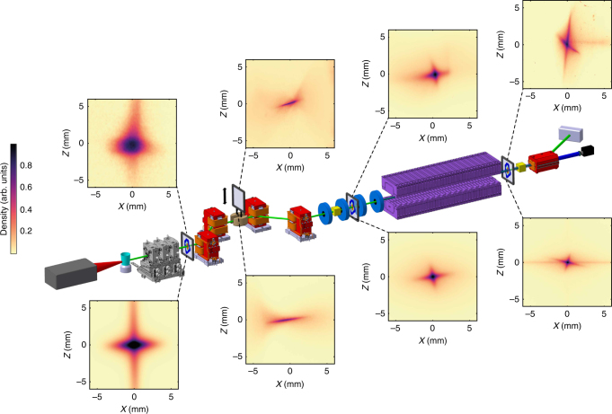
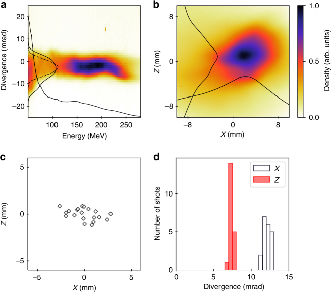
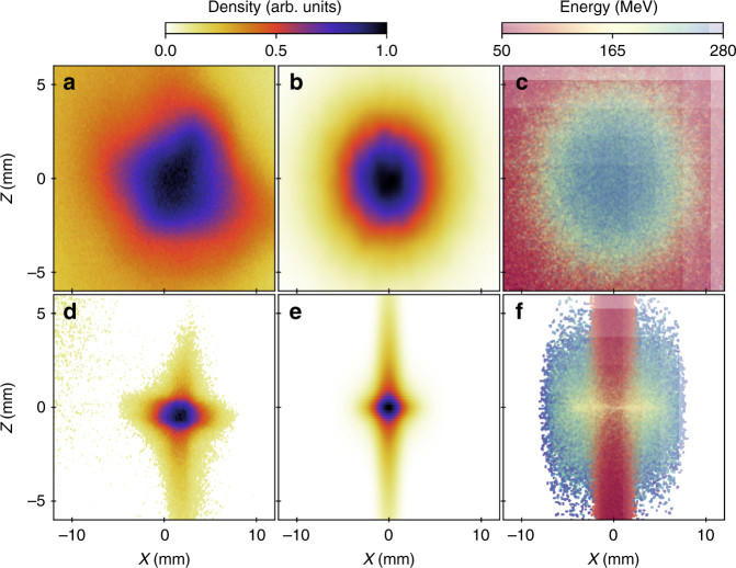
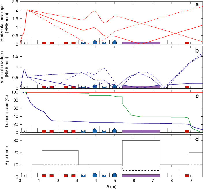
With gigaelectron-volts per centimetre energy gains and femtosecond electron beams, laser wakefield acceleration (LWFA) is a promising candidate for applications, such as ultrafast electron diffraction, multistaged colliders and radiation sources (betatron, compton, undulator, free electron laser). However, for some of these applications, the beam performance, for example, energy spread, divergence and shot-to-shot fluctuations, need a drastic improvement. Here, we show that, using a dedicated transport line, we can mitigate these initial weaknesses. We demonstrate that we can manipulate the beam longitudinal and transverse phase-space of the presently available LWFA beams. Indeed, we separately correct orbit mis-steerings and minimise dispersion thanks to specially designed variable strength quadrupoles, and select the useful energy range passing through a slit in a magnetic chicane. Therefore, this matched electron beam leads to the successful observation of undulator synchrotron radiation after an 8 m transport path. These results pave the way to applications demanding in terms of beam quality.


Conflict of interest statement

The authors declare no competing interests.

Figures

Fig. 1
Fig. 1
Scheme of the COXINEL manipulation line: laser hutch (grey), gas jet (cyan), removable permanent magnet quadrupoles (grey) which can be replaced by an electron spectrometer, magnetic chicane (dipole magnet in red) with a slit (brown) inserted in the middle of the chicane, electromagnetic quadrupoles (blue), undulator (purple), cavity beam position monitors (yellow), dipole dump (red), beam dump (grey) and CCD camera (black). LANEX and YAG screens for electron beam imagers. Measured (top) and simulated (down) electron beam transverse profiles (horizontal: x and vertical: z direction) along the line
Fig. 2
Fig. 2
Measured LWFA beam energy and transverse distribution without QUAPEVA. a Measurement with the spectrometer before the first screen, with corresponding energy profile and vertical divergence evaluated by superimposing the divergence in energy slices of ±1 MeV and renormalised to the charge in the given slice (solid line), and in the case of 176 ± 5 MeV (dashed line). b Electron beam transverse distribution observed on the first LANEX screen located at 64 cm from the source, without spectrometer, with corresponding horizontal and vertical profiles. c Shot-to-shot measured pointing stability and d associated statistics on the electron beam sizes
Fig. 3
Fig. 3
Electron beam transverse profiles observed on the first LANEX screen. Measured transverse profile without (a) and with (d) permanent magnet quadrupoles of variable strength (QUAPEVA). b, e Associated numerical simulations (see Methods section) of the transverse profile assuming a broadband energy spectrum spanning from 50 to 280 MeV and using the measured divergences and a screen resolution of 150 μm and simulated electron energy distribution in the transverse plane (c, f)
Fig. 4
Fig. 4
Electron beam properties along the line. a Horizontal and b vertical envelopes for 171 (dashed), 176 (solid) and 181 (dotted) MeV electron beam energies. c Losses along the line: 176 (red), 150 (green) MeV, spectrum from Fig. 2 (blue). d Horizontal (vertical) pipe diameter: dashed (solid). QUAPEVAs (grey), dipole (red), electromagnetic quadrupoles (blue), undulator (purple)
Fig. 5
Fig. 5
Beam pointing alignment compensation alignment method. Superimposed images with the appropriate adjustment of the QUAPEVA magnetic axis. a Case of screen in the middle of the chicane where the beam is horizontally dispersed, correction of the vertical dispersion (from I to II). On screen located at the undulator entrance: b initial beam (I), with artificial vertical dispersion introduced (II), with horizontal dispersion corrected (III), with artificial vertical dispersion removed (IV), c beam experimental transverse position control with respect to expected displacements from the model (black crosses)
Fig. 6
Fig. 6
Transverse profile of the electron beam for different quadrupole strengths. Electron beam optics focusing on the screen downstream the undulator without slit, for the 176 MeV reference case. Experimental, simulated profiles and associate modelled phase-space plot a mismatched case, c well-focused case with a 1.5% correction of QUAPEVA 2, variation of the gradients of all the quadrupoles (permanent magnet and electromagnetic) by −2% (b) and +2% (d)
Fig. 7
Fig. 7
Observation of undulator radiation. Measurement (a) and numerical modelling (b) of the radiation flux density normalised to 1 pC (without slit, bandpass filters and focusing lens). c Spectrum measured at the exit of the electron source (dotted), and simulated at the entrance of the undulator after transport in the line (dashed), with the 4 mm slit (solid curve). d On-axis resonant wavelength ranges without (blue) and with (red) slit, with electrons below 10% of the maximum charge excluded and spectral FWHM bandwidth of the optical filters. e Total photon count measured by a camera with a lens and normalised by the beam charge black stars: without slit and bandpass filter, downscaled by a factor 10; with a 4 mm slit, red circles: 300 nm, green diamonds: 253 nm, blue squares: 200 nm filter. Error bars: mean values and deviations of acquired data sets, solid curves: numerical simulation
Fig. 8
Fig. 8
Evolution of the normalised emittance along the transport line. a Horizontal and b vertical emittance for a ±1 MeV slice and for a ±5 MeV slice c, d without (blue) and with (red) magnetic defects for a reference beam of 1 mrad divergence (solid lines) and using measured divergences from Fig. 2a (dashed lines)

References

    1. Tajima T, Dawson JM. Laser electron accelerator. Phys. Rev. Lett. 1979;43:267–270. doi: 10.1103/PhysRevLett.43.267. - DOI
    1. Faure J, et al. A laser-plasma accelerator producing monoenergetic electron beams. Nature. 2004;431:541–544. doi: 10.1038/nature02963. - DOI - PubMed
    1. Geddes C, et al. High-quality electron beams from a laser wakefield accelerator using plasma-channel guiding. Nature. 2004;431:538–541. doi: 10.1038/nature02900. - DOI - PubMed
    1. Mangles S, et al. Monoenergetic beams of relativistic electrons from intense laser-plasma interactions. Nature. 2004;431:535–538. doi: 10.1038/nature02939. - DOI - PubMed
    1. Schlenvoigt HP, et al. A compact synchrotron radiation source driven by a laser-plasma wakefield accelerator. Nat. Phys. 2008;4:130–133. doi: 10.1038/nphys811. - DOI

Publication types

LinkOut - more resources