Review
. 2018 Aug;31(4):336-344.
doi: 10.1177/1971400918769911. Epub 2018 Apr 19.

A guide to identification and selection of axial planes in magnetic resonance imaging of the brain

Affiliations
Review

A guide to identification and selection of axial planes in magnetic resonance imaging of the brain

Shoichiro Otake et al. Neuroradiol J. 2018 Aug.

Abstract

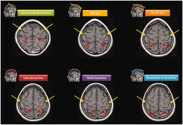
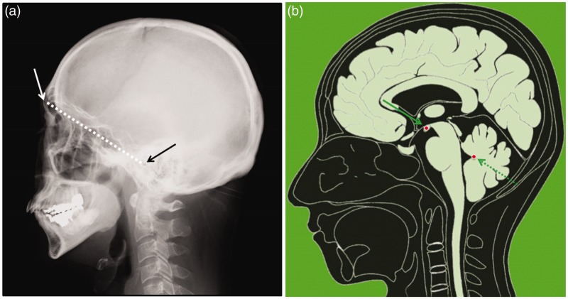
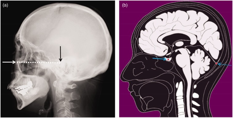
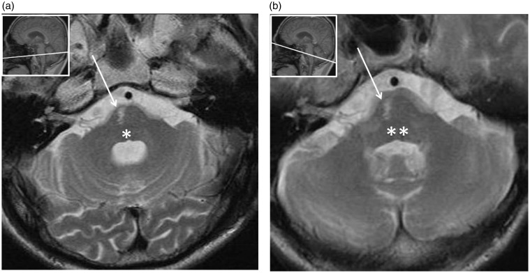
For brain magnetic resonance (MR) examination, three-dimensional imaging is commonly performed. Radiologists need to know the appropriate imaging angle for viewing. We present six imaging angles for the axial images. Each angle is determined by the reference line. The landmarks on the midsagittal MR image to determine the angle of the reference lines are as follows: the supraorbito-meatal line (the center of the mammillary body and the fastigium of the fourth ventricle), the orbito-meatal (OM) line (the center of the mammillary body and the most posterior point of the cerebellar tentorium), the Talairach anterior commissure (AC)-posterior commissure (PC) line (the superior edge of the AC and the inferior edge of the PC), the Schaltenbrand AC-PC line (the center of the AC and the center of the PC), the subcallosal line (the inferior border of the genu and the inferior border of the splenium of the corpus callosum), Reid's baseline (the center of the pituitary gland and the most posterior point of the cerebellar tentorium) and the brainstem vertical line (the line perpendicular to the posterior border of the brainstem). The AC-PC line is most commonly used in MR examination. The OM line is most commonly used in computed tomography examination. The supraorbito-meatal line is recommended for avoiding irradiation to the orbit. In cases of multiple sclerosis, the subcallosal line is recommended in the guidelines. For lesions in the orbital cavity, paranasal cavity or skull base, Reid's baseline is useful. For cases of brainstem lesions, the brainstem vertical line is useful.

Keywords: AC-PC line; Axial brain imaging; OM line; Reid’s baseline; brainstem vertical line; subcallosal line; supraorbito-meatal line.


Figures

Figure 1.
Figure 1.
The illustration shows the difference of angles of six axial reference lines. In order of the angle from acute to obtuse, the reference lines are: supraorbito-meatal (SM) line, orbito-meatal (OM) line, anterior commissure (AC)-posterior commissure (PC) line, subcallosal (SC) line, Reid’s baseline and brainstem vertical line.
Figure 2.
Figure 2.
Six axial images of different angles through the orbits. As the angle is changed, the structures of the posterior fossa range from the spinal cord to the cerebral peduncles.
Figure 3.
Figure 3.
Six axial images of different angles at the parietal region. As the angle is changed, the locations of the central sulci (yellow arrows) and pars marginalis (red arrows) gradually move from the anterior to the posterior.
Figure 4.
Figure 4.
(a) The supraorbito-meatal line on a skull X-ray passes through the most anterior point of the superior wall of the orbital cavity (white arrow) and the center of the external auditory meatus (black arrow). (b) The illustration of the midsagittal image shows that the landmarks of the supraorbito-meatal line are the center of the mammillary body (solid arrow) and the fastigium of the fourth ventricle (dotted arrow).
Figure 5.
Figure 5.
(a) The orbito-meatal (OM) line (dotted arrow) is used for positioning of Waters’ view (solid arrow). The angle from the OM line is 45 degrees. (b) The illustration of the midsagittal image shows that the landmarks are the center of the mammillary body (solid arrow) and the most posterior point of the cerebellar tentorium (dotted arrow). (c) On the axial image obtained by using these landmarks, the lens (arrow) and the external auditory meatus (arrowhead) are shown.
Figure 6.
Figure 6.
(a) The midsagittal MR image shows the AC (solid arrow) and PC (dotted arrow). (b) Among several kinds of the AC-PC lines, the Talairach AC-PC line and the Schaltenbrand AC-PC line are commonly used especially for stereotaxic surgery. The Talairach AC-PC line passes through the superior edge of the AC and the inferior edge of the PC (solid line). The Schaltenbrand AC-PC line passes through the center of the AC and the center of the PC (dotted line). (c) The illustration of the midsagittal image shows the AC (solid arrow) and PC (dotted arrow). For the Talairach AC-PC line, the landmarks are the superior edge of the AC and the inferior edge of the PC. For the Schaltenbrand AC-PC line, the landmarks are the center of the AC and the center of the PC. AC: anterior commissure; MR: magnetic resonance; PC: posterior commissure.
Figure 7.
Figure 7.
(a) The locations of the rostrum, genu and splenium of the corpus callosum are shown. (b) The illustration of the midsagittal image shows that the landmarks of the subcallosal line are the inferior border of the genu (solid arrow) and the inferior border of the splenium of the corpus callosum (dotted arrow).
Figure 8.
Figure 8.
(a) Reid’s baseline on a skull X-ray passes through the inferior border of the orbital cavity (white arrow) and the superior border of the external auditory meatus (black arrow). (b) The illustration of the midsagittal images shows that the landmarks of Reid’s baseline are the center of the pituitary gland (solid arrow) and the most posterior point of the cerebellar tentorium (dotted arrow).
Figure 9.
Figure 9.
(a) The illustration of the midsagittal image shows that the landmark of the brainstem vertical line is the perpendicular line (blue dotted line) to the posterior border of the brainstem (red dotted line). (b) The slice parallel to the anterior commissure-posterior commissure line (dotted line) includes both the pons (*) and the medulla oblongata (**). Therefore, the diagnosis about the location of a lesion tends to be misunderstood.
Figure 10.
Figure 10.
A 72-year-old male presented with pontine ventral infarction. (a) On the T2-weighted brainstem vertical plane, it is clear that the lesion is at the level of the pons (*). (b) On the T2-weighted anterior commissure-posterior commissure plane, the lesion might be misinterpreted to be at the level of the medulla oblongata (**).
Figure 11.
Figure 11.
A 79-year-old male presented with medial longitudinal fasciculus (MLF) syndrome due to upper pontine tegmental infarction. (a) T2-weighted brainstem vertical plane at the level of the upper pons. (b) The lesion is shown at the level of the upper pons; therefore, MLF syndrome can be diagnosed. (c) T2-weighted anterior commissure-posterior commissure plane at the level of the cerebral peduncles. (d) The lesion is shown at the level of the midbrain; therefore, the diagnosis of MLF syndrome might be difficult.

References

    1. Lund E, Halaburt H. Irradiation dose to the lens of the eye during CT of the head. Neuroradiology 1982; 22: 181–184. - PubMed
    1. Yeoman LJ, Howarth L, Britten A, et al. Gantry angulation in brain CT: Dosage implications, effect on posterior fossa artifacts, and current international practice. Radiology 1992; 184: 113–116. - PubMed
    1. Smith AN, Shah GA. A survey of routine head CT protocols in Australia. Br J Radiol 1997; 70: 372–374. - PubMed
    1. Otake S, Yamana D, Mizutani H, et al. Reference lines for oblique axial MR imaging of the brain. Radiology 1996; 198: 906–907. - PubMed
    1. Nowinski WL. Modified Talairach landmarks. Acta Neurochir 2001; 143: 1045–1057. - PubMed

MeSH terms

LinkOut - more resources