. 2018 Jun;75(6):258-280.
doi: 10.1002/cm.21448.

Axonal neurofilaments exhibit frequent and complex folding behaviors

Affiliations

Axonal neurofilaments exhibit frequent and complex folding behaviors

J Daniel Fenn et al. Cytoskeleton (Hoboken). 2018 Jun.

Abstract

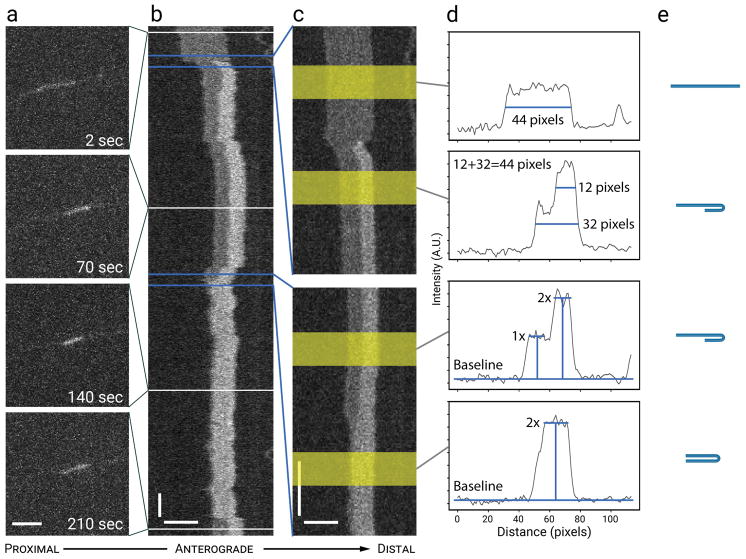
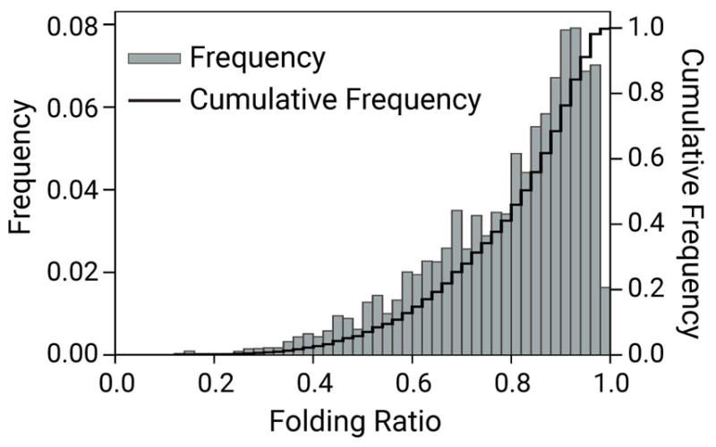
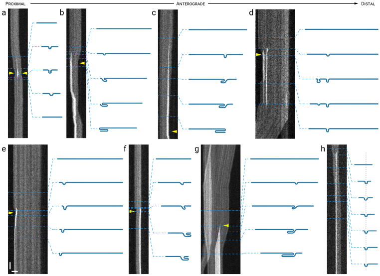
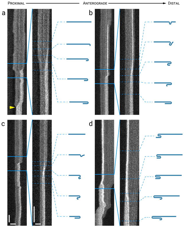
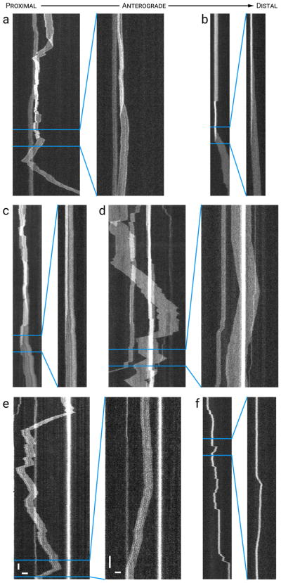
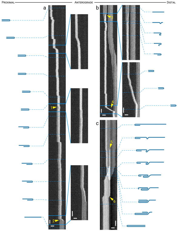
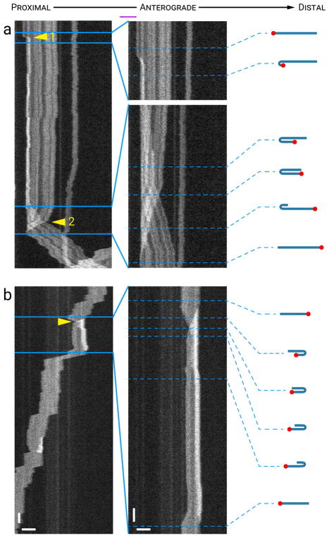
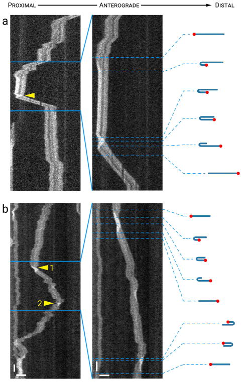
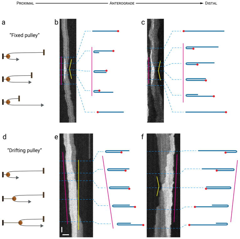
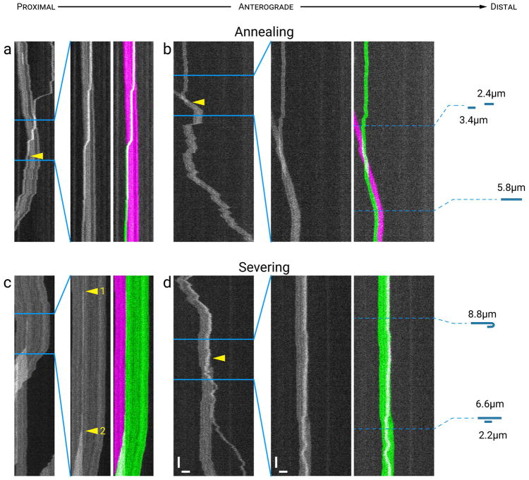
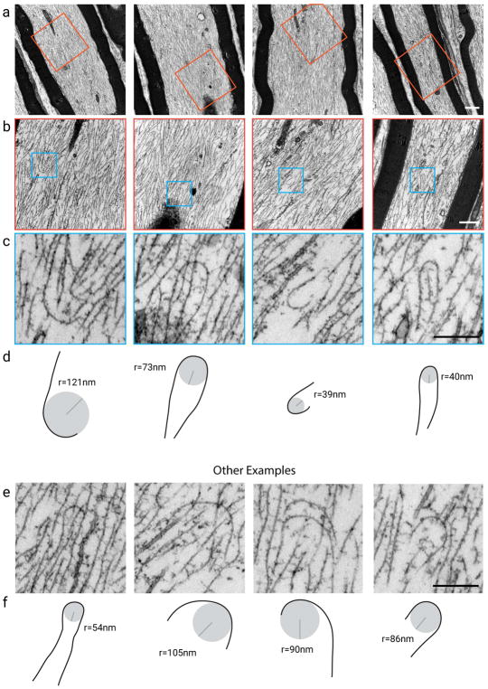
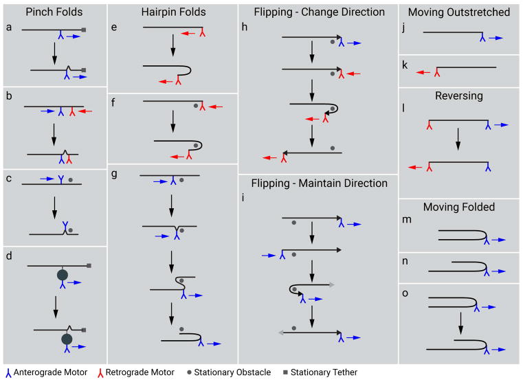
Neurofilaments are flexible cytoskeletal polymers that are capable of folding and unfolding between their bouts of bidirectional movement along axons. Here we present a detailed characterization of this behavior in cultured neurons using kymograph analysis with approximately 30 ms temporal resolution. We analyzed 781 filaments ranging from 0.6-42 µm in length. We observed complex behaviors including pinch folds, hairpin folds, orientation changes (flips), and occasional severing and annealing events. On average, the filaments spent approximately 40% of their time in some sort of folded configuration. A small proportion of filaments (4%) moved while folded, but most (96%) moved in an outstretched configuration. Collectively, our observations suggest that motors may interact with neurofilaments at multiple points along their length, but preferentially at their ends. In addition, the prevalence of neurofilament folding and the tendency of neurofilaments to straighten out when they move, suggest that an important function of the movement of these polymers in axons may be to maintain them in an outstretched and longitudinally co-aligned configuration. Thus, neurofilament movement may function as much to organize these polymers as to move them, and this could explain why they spend so much time engaged in apparently unproductive bidirectional movement.

Keywords: annealing; axonal transport; kymograph; neurofilament; severing.


Figures

Figure 1
Figure 1. Analysis of neurofilament folding
(a) Raw images from a 10,000-frame movie. Scale bar, 5 μm. (b) A time-compressed kymograph (compressed in the vertical dimension) for the filament shown in (a). The horizontal white lines represent the positions of the raw images in (a). The changes in length and intensity associated with neurofilament folding are hard to discern in the raw images due to the low signal-to-noise ratio, but they are readily apparent in the kymograph due to the spatial alignment of the linear intensity profiles. Horizontal scale bar, 5 μm. Vertical scale bar, 10 s. (c) Two regions of the kymograph in (b), indicated by the blue lines, magnified (i.e. without time compression) to provide higher temporal resolution. In the top panel, the increase in the brightness of the filament at the right (distal) end is accompanied by a decrease in the apparent filament length. In the bottom panel, the filament shortens further to about 50% of its original length, as if folded in half. Horizontal scale bar, 5 μm. Vertical scale bar, 1 s. (d) Linear intensity profiles from the regions highlighted in yellow in (c). The thickness of the yellow bands (20 pixels) represents the time window that was sampled to generate the average intensity profile. The average intensity is shown in arbitrary units (A.U.). The top two panels show the measurement of filament length. The bottom two panels show the measurement of filament intensity, extending from the baseline to plateau within the folded and unfolded regions. These measurements confirm that the distal end of the filament folded back on itself to create a hairpin fold, with a doubling in the filament intensity in the region of overlap. (e) Schematic of the inferred folding configuration. Note that the filament length is conserved throughout the folding process, consistent with the intensity and length measurements in (d). See Movie S1 in Supplementary Data for an excerpt from the raw unprocessed movie upon which this figure is based. [Color figure can be viewed at wileyonlinelibrary.com]
Figure 2
Figure 2. Prevalence and extent of neurofilament folding
For each filament, we calculated the filament length in each timeframe of the kymograph and expressed each of these lengths as a fraction of the maximum filament length for all timeframes for that filament (see Methods). For example, a filament that was folded in half would have a folding ratio of 0.5. Note that this analysis is blind to the configuration of the folded filaments; it simply measures the extent of folding. The folding ratios for all filaments at all time points were then pooled and binned to generate the resulting histogram (bars) and cumulative histogram (stepped line). Note that these are time-weighted distributions in which each filament is represented in proportion to the number of time frames for which it was tracked. Data from 781 filaments across 301 kymographs, representing a total tracking time of 3,775,141 timeframes (~79 hours of tracking time).
Figure 3
Figure 3. Pinch folds
The drawings represent our interpretation of the folding configuration based on measurements of filament length and intensity. The lengths of the filaments in the drawings are drawn to relative scale within each kymograph, but not between kymographs. (a) A transient pinch fold that formed near the center of a filament, appearing to pull both ends of the filament inwards (arrowheads). (b) A pinch fold that formed near the proximal end of a filament and then evolved into what appears to be a double hairpin fold, appearing to pull the opposite (distal) end inwards (arrowhead) more than the proximal end. (c) A pinch fold that formed near the distal end of a filament and then evolved into what appears to be a double hairpin fold, appearing to pull the distal end inwards (arrowhead). (d) Two transient pinch folds that formed in close proximity to each other near the proximal end of a filament, appearing to pull the proximal end inwards (arrowhead) in the anterograde direction. The folds subsequently resolved when the proximal end of the filament moved back in the opposite (retrograde) direction. (e) A pinch fold that formed near the proximal end of a filament, appearing to pull the proximal end of the filament inwards (arrowhead) and then translocated toward the proximal end as the filament unfolded. (f) A pinch fold that formed near the distal end of a filament and then evolved into what appeared to be a double hairpin fold, pulling the opposite end of the filament inward. (g) A pinch fold (arrowhead) that formed near the middle of a filament, and then evolved into a double hairpin fold, appearing to pull both the proximal and distal ends of the filament inwards in the process. Note the increase in brightness on the left, which represents overlap of the proximal end of the filament of interest with a shorter filament that paused and then moved away in a retrograde direction. (h) A pinch fold along a moving filament. The pinch fold remained stationary and the filament appeared to “feed through” the pinch as it translocated distally. Horizontal scale bar, 5 μm. Vertical scale bar, 1 s. See Movies S2 and S3 in Supplementary Data for animations of the filaments in (g) and (h). [Color figure can be viewed at wileyonlinelibrary.com]
Figure 4
Figure 4. Hairpin folds
Each panel shows a time-compressed kymograph (left) and a portion of that kymograph without time compression (right). The drawings represent our interpretation of the folding configuration based on measurements of filament length and intensity. The lengths of the filaments in the drawings are drawn to relative scale within each kymograph. (a) A hairpin fold that formed at the distal end of a filament and progressed until the filament was folded in half (arrowhead). (b,c) Evolution of a pinch fold into a double hairpin fold and then subsequently into a single hairpin fold. (d) Unfolding of a double hairpin fold close to the proximal end of a filament into a single hairpin fold. Horizontal scale bars, 5 μm. Left vertical scale bar, 5 s. Right vertical scale bar, 1s. See Movie S4 in Supplementary Data for an animation of the filament in (a). [Color figure can be viewed at wileyonlinelibrary.com]
Figure 5
Figure 5. Most filaments unfold when they move
Each panel shows a time-compressed kymograph (left) and a portion of that kymograph without time compression (right). (a–c) Examples of filaments that folded into complex and compact configurations yet stretched out when they moved. (d–f) Examples of filaments that exhibited numerous repeated reversals while remaining outstretched. Note that the filaments often changed direction abruptly (within tens of milliseconds) without folding, as if shuttling backwards and forwards. Horizontal scale bars, 5 μm. Left vertical scale bar, 5 s. Right vertical scale bar, 1 s. See Movie S5 in Supplementary Data for an animation of the filament in (d). [Color figure can be viewed at wileyonlinelibrary.com]
Figure 6
Figure 6. Rare examples of filaments that moved while folded
Panels (a) and (b) each show a time-compressed kymograph (left) and a portion of that kymograph without time compression (right). Panel (c) shows only an uncompressed kymograph. The drawings represent our interpretation of the folding configuration based on measurements of filament length and intensity. The lengths of the filaments in the drawings are drawn to relative scale within each kymograph, but not between kymographs. (a) A filament that entered the kymograph window folded in half in a hairpin configuration and moved rapidly but intermittently in an anterograde direction with the hairpin bend leading before unfurling partially into a two-thirds folded configuration (arrowhead 1). It then continued to move anterogradely with the hairpin bend still leading, but with the bend at a new location along the length of the filament, and then it unfurled completely (arrowhead 2), revealing its length when fully outstretched. Horizontal scale bar, 5 μm. Left vertical scale bar, 5 s. Right vertical scale bar, 1 s. (b) An outstretched filament that folded in half in a hairpin configuration (arrowhead 3) while pausing and then moved anterogradely (arrowhead 4) while still folded, with the hairpin bend leading. Horizontal scale bars, 5 μm. Left vertical scale bar, 5 s. Right vertical scale bar, 1 s. (c) A pinch fold that formed in the center of a filament (arrowhead 5) and then moved retrogradely, pulling the filament into a hairpin fold. The filament paused briefly and then moved retrogradely again while folded in half (arrowhead 6). Horizontal scale bars, 5 μm. Vertical scale bar, 1 s. See Movie S6 in Supplementary Data for an animation of the filament in (c). [Color figure can be viewed at wileyonlinelibrary.com]
Figure 7
Figure 7. Flipping
Each panel shows a time-compressed kymograph (left) and portions of that kymograph without time compression (right). The drawings represent our interpretation of the folding configuration based on measurements of filament length and intensity. The red dots mark one end of the filament to facilitate tracking it during the flipping event. The lengths of the filaments in the drawings are drawn to relative scale within each kymograph, but not between kymographs. (a) A hairpin fold that progressed to a flipping event. The filament was fully extended initially and then formed a hairpin fold at its proximal end (arrowhead 1) about 8 s after the start of the kymograph. Approximately one minute later, this proximal end of the filament resumed movement in the anterograde direction eventually moving past the distal end of the filament (arrowhead 2). As a result, the filament switched orientation within the axon, a fact confirmed by inspection of the barcoding pattern seen along this filament. (b) A filament that moved retrogradely, flipped its orientation, and then resumed movement in the same direction with what was the trailing end now leading. The arrowhead indicates the location where the proximal end became the distal end, and vice versa. Horizontal scale bars, 5 μm. Left vertical scale bar, 5 s. Right vertical scale bar, 1 s. See Movie S7 in Supplementary Data for an animation of the filament in (a). [Color figure can be viewed at wileyonlinelibrary.com]
Figure 8
Figure 8. Flipping accompanied by reversals
Each panel shows a time-compressed kymograph (left) and portions of that kymograph without time compression (right). The drawings represent our interpretation of the folding configuration based on measurements of filament length and intensity. The red dots mark one end of the filament to facilitate tracking it during the flipping event. The lengths of the filaments in the drawings are drawn to relative scale within each kymograph, but not between kymographs. (a) A filament that moved retrogradely, alternating between bouts of rapid movement and short pauses, then flipped its orientation (arrowhead) and moved anterogradely (retrograde-flip-anterograde). (b) A filament that exhibited two flipping events, each associated with a change in the direction of movement; first from retrograde to anterograde (arrowhead 1) and then from anterograde to retrograde (arrowhead 2). Horizontal scale bars, 5 μm. Left vertical scale bar, 5 s. Right vertical scale bar, 1 s. See Movie S8 in Supplementary Data for an animation of the filament in (a). [Color figure can be viewed at wileyonlinelibrary.com]
Figure 9
Figure 9. Wrap-around behavior during flipping
Examples of flipping events where the filaments appear to wrap around an invisible point at the apex of the hairpin fold, like a rope feeding through a pulley. The drawings represent our interpretation of the folding configuration based on measurements of filament length and intensity. The lengths of the filaments in the drawings are drawn to relative scale within each kymograph, but not between kymographs. (a, b, c) Schematic and two examples where the apex of the hairpin bend remained fixed (magenta lines) as the filament fed through the bend (“fixed pulley”), causing one end of the filament to move toward the bend as the other moved away (yellow lines). (d, e, f) Schematic and two examples where the apex of the hairpin bend drifted (magenta line) as the filament fed through the bend (“drifting pulley”). In (e), one filament end remained stationary (yellow line) as though tethered, whereas in (f) both ends moved (yellow line). Horizontal scale bar, 5 μm. Vertical scale bar, 1 s. See Movie S9 in Supplementary Data for an animation of the filament in (b). [Color figure can be viewed at wileyonlinelibrary.com]
Figure 10
Figure 10. Annealing and severing
Examples of annealing and severing events. Each panel shows a time-compressed kymograph (left) and portions of that kymograph without time compression (right). The drawings depict the parent and daughter filaments drawn to relative scale. (a) A short retrogradely moving filament crossed paths with a longer anterogradely moving filament and the two then joined together (arrowhead) and moved retrogradely as one filament. The length of the daughter filament (10.5 μm) was equal to the sum of the two parent filaments (1.5 and 9 μm). (b) A short anterogradely moving filament crossed paths with a short pausing filament and the two then joined together (arrowhead) and moved anterogradely as one filament. The length of the daughter filament (5.8 μm) was equal to the sum of the two parent filaments (2.4 and 3.4 μm). (c) A long filament moved anterogradely, then paused and severed into two daughter filaments. The longer daughter filament then moved retrogradely (opposite to the direction of movement of the parent filament) and passed the shorter daughter filament, which remained paused. The length of the parent filament (20.7 μm) was equal to the sum of the two daughter filaments (13.8 and 6.9 μm). The increase in brightness marked by arrowhead 1 was either a pinch fold at the future site of severing, or overlap between the two daughter filaments after severing (see text). Severing is evident when the filaments physically separate (arrowhead 2). (d) A filament with a short hairpin fold at its distal end moved anterogradely, paused, and then severed into two daughter filaments at the apex of the hairpin bend. The arrowhead marks the apparent severing event which appeared to occur at the apex of the hairpin bend. The length of the parent filament (8.8 μm) was equal to the sum of the lengths of the daughter filaments (6.6 and 2.2 μm). Horizontal scale bars, 5 μm. Leftvertical scale bar, 5 s. Right vertical scale bar, 1 s. See Movie S10 in Supplementary Data for an animation of the filament in (d). [Color figure can be viewed at wileyonlinelibrary.com]
Figure 11
Figure 11. Filament folding in vivo
Transmission electron microscopy of large myelinated axons in the tibial nerve from an adult mouse (longitudinal sections, approximately 65 nm thick). (a) Low magnification views of four different axons. Images acquired at an instrument magnification of 17,000. Scale bar, 1 μm. (b) High magnification views of the regions represented by the orange boxes in (a). Images acquired at an instrument magnification of 39,000. Note that the field of view is rotated due to the helical path of the electron beam. Scale bar, 0.5 μm. (c) Enlarged views of the regions represented by the blue boxes in (b). Scale bar, 0.25 μm. (d) Drawings of the folded filaments in (c), showing their approximate apparent radius of curvature in 2D projection. (e) Four additional examples of folded filaments obtained from other axonal sections. Scale bar, 0.25 μm. (f) Drawings of the folded filaments in (e), showing their approximate apparent radius of curvature in 2D projection (see discussion of caveats in text). [Color figure can be viewed at wileyonlinelibrary.com]
Figure 12
Figure 12. Potential mechanisms of neurofilament folding
Schematic diagram depicting how forces acting on neurofilaments could explain the diversity of neurofilament folding behaviors. The neurofilaments are represented as horizontal black lines. For the flipping events, one end of the filament is marked with an arrowhead to facilitate tracking of filament orientation. Proximal is left and distal is right throughout. Anterograde and retrograde motors are represented in blue and red, respectively, and the movement of these motors is represented with blue and red arrows. The gray dots represent hypothetical stationary obstacles around which filaments could wrap. The gray squares represent hypothetical stationary objects to which filaments could be tethered. (a) A pinch fold could represent a “buckling” of a filament at the site of motor attachment if one end of the filament is tethered. The tethering site is depicted here as being at the distal end of the filament, but it could be at any site along the filament distal to the site of motor attachment. (b) A pinch fold could also arise if motors of opposing directionality attach to a filament and move towards each other. (c) At least some pinch folds appeared to be generated by a motor pulling the filament from the middle against some obstacle, since pinch folds often evolved into hairpin folds (g). (d) Motors could also act indirectly to generate folding, such as via a membranous organelle that links transiently to the filament as it moved past it. (e) Hairpin folds could form if a retrograde motor engaged with the distal end of a filament to form a distal hairpin (shown here) or an anterograde motor engaged with the proximal end to form a proximal hairpin (not shown). (f) In some cases, the apex of the hairpin bend remained fixed in place during the evolution of the hairpin fold, implying that the filament wrapped around some obstacle in the axon. (g) A pinch fold in the interior of a filament could evolve into a double hairpin fold by a motor pulling the filament around an obstacle. (h) Some filaments changed their direction of movement while simultaneously flipping their proximal/distal orientation. In this example a retrograde motor binds to the distal end of an anterogradely moving filament, reversing the orientation and direction of movement of the filament. Note that the leading end of the filament (black arrowhead) remains the same. (i) Flipping also occurred without a change of directionality. In this case, an anterograde motor binds to the trailing end of an anterogradely moving filament and then pulls the trailing end forwards so that what was the leading end (black arrowhead) is now the trailing end (gray arrowhead). (j,k) The majority of filaments moved in a fully outstretched configuration which implies that motors were bound to their leading ends. (l) Given their flexibility, the movement of filaments in a fully outstretched configuration during reversals implies that motors of opposing directionality can engage with opposite ends of the same filament. The speed of these reversals suggests that these motors could be bound simultaneously (as shown here). (m, n, o) The rare movement of filaments in a hairpin configuration indicates that motors can also bind along the length of the filament, not just at the filament ends. The two arms of the hairpin are equal in length if the motor binds in the middle of the filament (m) and unequal in length if it binds closer to one end than the other (n). In some cases, filaments were observed to transition from the former to the latter or vice versa (o). Overall, these folding behaviors suggest that both anterograde and retrograde motors can engage directly or indirectly with neurofilaments at multiple sites all along their length but with a preference for an association with the filament ends. [Color figure can be viewed at wileyonlinelibrary.com]

References

    1. Beck R, Deek J, Jones JB, Safinya CR. Gel-expanded to gel-condensed transition in neurofilament networks revealed by direct force measurements. Nat Mater. 2010a;9(1):40–6. - PubMed
    1. Beck R, Deek J, Choi MC, Ikawa T, Watanabe O, Frey E, Pincus P, Safinya CR. Unconventional salt trend from soft to stiff in single neurofilament biopolymers. Langmuir. 2010b;26(24):18595–9. - PubMed
    1. Brown A. Slow axonal transport: stop and go traffic in the axon. Nat Rev Mol Cell Biol. 2000;1:153–56. - PubMed
    1. Brown A. Slow axonal transport. In: Caplan M, editor. Reference Module in the Biomedical Sciences. Elsevier; 2014.
    1. Brown A. Axonal transport. In: Pfaff DW, Volkow ND, editors. Neuroscience in the 21st century: from basic to clinical. New York: Springer Publishing; 2015. pp. 333–79.

Publication types