. 2018 Jun;21(6):881-893.
doi: 10.1038/s41593-018-0139-8. Epub 2018 Apr 30.

Precise multimodal optical control of neural ensemble activity

Affiliations

Precise multimodal optical control of neural ensemble activity

Alan R Mardinly et al. Nat Neurosci. 2018 Jun.

Abstract

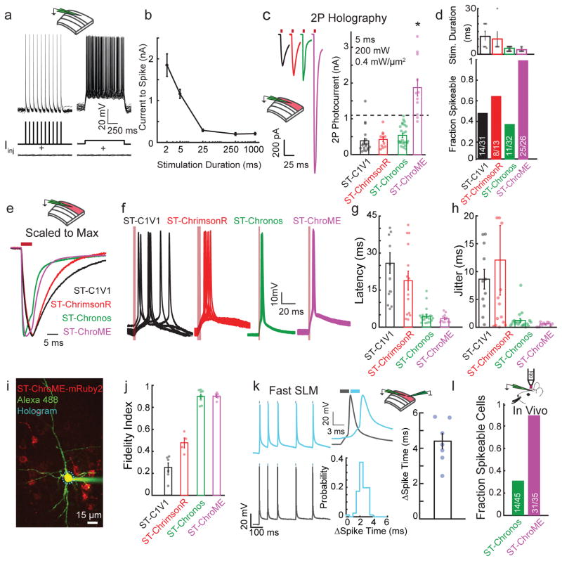
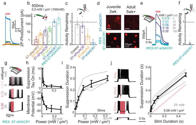
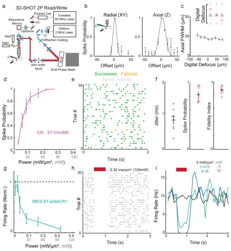
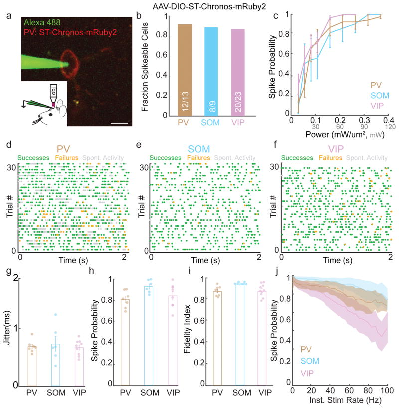
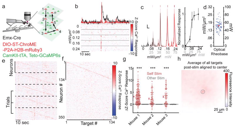
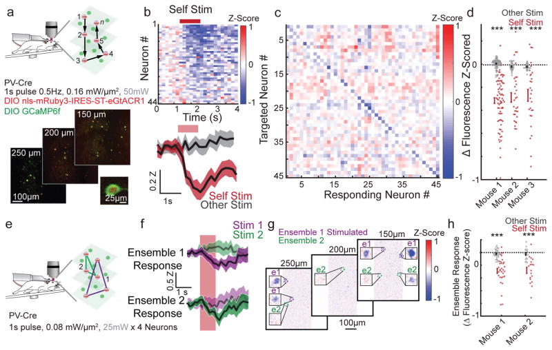
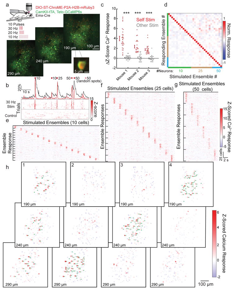
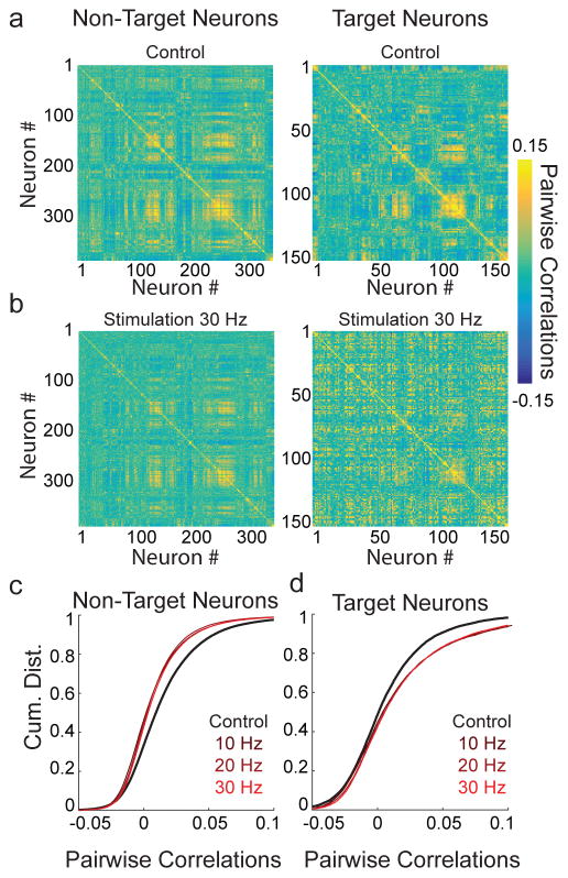
Understanding brain function requires technologies that can control the activity of large populations of neurons with high fidelity in space and time. We developed a multiphoton holographic approach to activate or suppress the activity of ensembles of cortical neurons with cellular resolution and sub-millisecond precision. Since existing opsins were inadequate, we engineered new soma-targeted (ST) optogenetic tools, ST-ChroME and IRES-ST-eGtACR1, optimized for multiphoton activation and suppression. Employing a three-dimensional all-optical read-write interface, we demonstrate the ability to simultaneously photostimulate up to 50 neurons distributed in three dimensions in a 550 × 550 × 100-µm3 volume of brain tissue. This approach allows the synthesis and editing of complex neural activity patterns needed to gain insight into the principles of neural codes.


Conflict of interest statement

Competing Interest Statement

The authors declare that they have no competing interests.

Figures

Figure 1
Figure 1. ST-ChroME allows precise high-fidelity 2P activation
a) Overlay of 25 trials from a representative L2/3 pyramidal neuron showing the Vm response to 5 ms current pulses or sustained current injection near the neuron’s rheobase. b) Current needed to induce action potentials as a function of stimulus duration (n = 8 L2/3 pyramidal neurons). c) Left, grand average photocurrent traces from neurons expressing ST-C1V1T/T (black, n = 19), ST-ChrimsonR (red, n =11), ST-Chronos (green, n =25), or ST-ChroME (magenta, n=11), via IUE. Right, photocurrent amplitudes elicited by CGH stimulation. Dashed line represents mean rheobase for 5 ms stimulation of L2/3 pyramidal neurons (ST-ChroME vs others: p<0.0008, Kruskal-Wallis test with multiple comparisons correction, all others comparisons p>0.13). d) Top, duration of CGH stimulation needed to elicit action potentials in neurons expressing each opsin (n = 8 ST-C1V1, n = 5 ST-ChrimsonR, n=25 ST-Chronos, n= 8 ST-ChroME). Bottom, fraction of electroporated L2/3 neurons that could be driven at 1 Hz with best CGH stimulation. e) Traces shown in (c) scaled to the peak current amplitude for each. f) 10 overlaid traces from representative L2/3 neurons expressing ST opsins during 1 Hz CGH stimulation (red line indicates light pulses). g) Spike latency for 1 Hz CGH stimulation of L2/3 neurons expressing ST-Opsins. ST-C1V1 T/T 25.9±4 ms (n=15), ST-ChrimsonR 18.8±3.8 ms (n=14), ST-Chronos 4.4±0.65 ms (n=23), ST-ChroME 3.48±0.49 ms (n = 12). ST-ChroME vs ST-C1V1 T/T, p=0, vs ST-ChrimsonR p=0.0028; vs ST-Chronos p = 0.95, by Kruskal-Wallis test with multiple comparisons correction. h) Jitter for 1 Hz CGH stimulation of neurons expressing ST-Opsins. ST-C1V1 T/T 8.6±1.8 ms (n=11), ST-ChrimsonR 12±6.3 ms (n=14), ST-Chronos 1.2±0.36 ms (n=20), ST-ChroME 0.54±0.1 ms (n=10). ST-ChroME vs ST-C1V1 T/T, p=0.0011, vs ST-ChrimsonR p=0.048; vs ST-Chronos p = 0.7 by Kruskal-Wallis test with multiple comparisons correction. i) Two-photon image of whole cell recording from L2/3 pyramidal neuron expressing ST-ChroME-mRuby2 (image representative of n=10 ST-ChroME-mRuby2 neurons). j) Fidelity index in response to Poisson-like stimulation. ST-ChroME (n=7) vs ST-C1V1 T/T (n = 6), p = 0, vs ST-ChrimsonR (n=4), p= 0, vs ST-Chronos (n=9), p = 0.99, by Kruskal-Wallis test with multiple comparisons corrections. k) Left, representative traces of two simultaneously recorded ST-ChroME expressing neurons stimulated with an identical Poisson train for 2.5 ms with a temporal offset of 3 ms. Top middle, example light-evoked spikes in the two neurons. Middle bottom, distribution of the difference in spike times from an example pair of neurons. Right, difference in mean spike times for n = 7 pairs. l) Bar graph showing the fraction of neurons expressing ST-Chronos (green) or ST-ChroME (magenta) that could be optogenetically driven in vivo (p=0.0089, two-sided Fisher Exact Test). All data represent mean and s.e.m.
Figure 2
Figure 2. Fast and potent holographic suppression of neural activity
a) Example average traces of whole cell photocurrents elicited by 500 ms (100 mW, 0.2 mW/μm2) CGH stimulation from CHO cells held at 0 mV expressing inhibitory ST-opsins color-coded as in (b). b) Mean photocurrent elicited during a 500 ms stimulation, as in (a), plotted on a log scale. (n=5 cells expressing ST-eNpHR3, n=8 ST-eArch3, n=9 ST-ePsuACR, n=8 ST-eiC++, n=5 ST-eGtACR1, n=10 IRES-ST-eGtACR1) c) In vivo firing activity that persists during optogenetic suppression of L2/3 neurons expressing ST-opsins. Each dot represents mean activity for a single neuron (5–60 sweeps per cell). n=7 no opsin control, n=6 ST-ePsuACR, n=8 ST-eArch3, n=10 ST-eGtACR1. d) Example confocal images from juvenile (14–15 days old) and adult (35+ days old) mice expressing ST-eGtACR1-mRuby2 or H2b-mRuby3 IRES-ST-eGTACR1. Imaging conditions are matched within an opsin. Representative image from 3 mice each condition. e) Example whole cell voltage clamp recording of a L2/3 neuron expressing IRES-ST-eGtACR1 held at 0 mV and stimulated for 500 ms with varying illumination powers. f) In vivo activity that persists during optogenetic suppression with IRES-ST-eGtACR1 using 3D-SHOT (0.32mW/μm2, 100 mW), presented as in (c). (n=9 IRES-ST-eGtACR1 cells) g) Overlay of 30 current clamp traces from a L2/3 pyramidal neuron expressing IRES-ST-eGtACR1 during current injection, aligned to the onset of a 50 ms stimulation at three different power levels. h) Top, as in (g), the time for suppression to take effect calculated for a 50 ms light stimulation. Reported as the tau of a fit to the observed number of action potentials after light onset in 1ms bins, assuming a Poisson noise model (n=6 neurons). Bottom, membrane potential of each neuron during the last 10 ms of a 50 ms stimulus as a function of stimulus intensity (n=6 neurons). i) Duration of suppression, defined as the mean time until the next action potential as a function of stimulus intensity. Grey bars indicate individual replicates, black mean and s.e.m. (n=6 neurons). j) Left, overlay of 30 whole cell current clamp traces during light stimulation of different durations. Bottom, schematic of current injection where onset of current injection was varied with respect to the light stimulus. Right, quantification of the duration of suppression as a function of stimulus duration. Grey bars indicate individual replicates, black mean (n=6 neurons). All data represent mean and s.e.m.
Figure 3
Figure 3. Creating and editing spatiotemporal neural activity in vivo
a) Simplified schematic of light path allowing simultaneous 2P imaging and 3D-SHOT photostimulation. b) Physiological point spread function (PPSF) of 3D-SHOT stimulation of neurons measured by in vivo loose patch. Left, spike probability for radial (XY) axis; right for axial (Z) axis (n=3 neurons). c) In vivo recording of 3D-SHOT’s axial PPSF as a function of distance from the system’s zero order. PPSFs were measured as a function of depth by testing the spiking response to digital defocusing of the hologram while mechanically offsetting the objective varying distances from the focal plane (n=3 neurons). d) Spike probability as a function of stimulation power in vivo for 1Hz stimulation in L2/3 pyramidal neurons expressing ST-ChroME-mRuby2 via IUE (n = 10 neurons). e) Representative experiment showing in vivo Poisson stimulation of a L2/3 neuron expressing ST-ChroME. f) Jitter, spike probability, and fidelity index score for Poisson stimulation of L2/3 neurons expressing ST-ChroME (n = 7 neurons). g) Firing rate of neurons during stimulation normalized to pre-stimulation rate and measured through in vivo loose patch recordings from cells expressing IRES-ST-eGtACR1 (n=9 neurons). h) Representative raster plot from a neuron suppressed with 500 ms stimulation. i) Representative histogram of firing rate during IRES-ST-eGtACR1 suppression at several stimulation powers for the same neuron as in (h). Each line is the mean of 25+ stimulations binned at 100ms. All data indicate mean and s.e.m.
Figure 4
Figure 4. Spatiotemporal activation of cortical inhibition
a)Example image of in vivo loose patch recording of a PV-neuron expressing AAV-ST-Chronos-mRuby2 (scalebar = 10 μm). b) Fraction of PV, SOM, and VIP neurons expressing AAV-DIO-ST-Chronos-mRuby2 that could be induced to fire action potentials in vivo using 3D-SHOT. c) Line plots showing mean spike probability at 1 Hz as a function of stimulation power for inhibitory neurons expressing ST-Chronos (PV: n = 10, SOM: n = 7, VIP: n= 14 cells). d–f) Representative experiments showing in vivo 3D-SHOT Poisson stimulation of PV (30 Hz), SOM (10 Hz), or VIP (10 Hz) neurons expressing ST-Chronos (green: light-evoked action potentials, orange: failures, gray: spontaneous activity). g–i) Bar graphs indicating the jitter, spike probability, and fidelity index score for 3D-SHOT Poisson stimulation of PV, SOM, or VIP neurons expressing ST-Chronos (PV: n = 7, SOM: n = 7, VIP: n = 9 cells). j) Spike probability as a function of instantaneous stimulation frequency for PV (brown), SOM (blue), or VIP (purple) neurons undergoing Poisson-stimulation in vivo (PV: n = 7, SOM: n = 7, VIP: n = 9 cells). All data represent mean and s.e.m.
Figure 5
Figure 5. All-optical read/write with high spatiotemporal fidelity
a) Schematic illustrating single-cell 3D all-optical read/write experiments performed in head-fixed mice freely running on a circular treadmill. b) Example optical rheobase experiment (10 × 5ms pulses at 30 Hz) with varying light intensity using 3D-SHOT. Top, example dF/F calcium trace (black) or deconvolution (red). Below, raster plots of z-scored deconvolved calcium traces. c) Left, average deconvolved calcium traces from an optical rheobase experiment (shaded area indicates 95% CI, scale bars represent 10% max response and 1 second). Right, the example neurons’ all-optical response function. d) Power intensity needed to approach saturation of the all-optical response function (80% of maximum, n = 96 neurons, representative experiment from N = 3 mice). e) Five consecutive trials of sequential stimulation of n=134 neurons from a representative experiment. Each panel corresponds to one trial (separated by dashed lines), and each line shows the trial-wise z-scored deconvolved calcium response for each neuron (see colorbar on f). Neurons were stimulated at 2 Hz with 10 × 5 ms pulses at 30 Hz. f) Mean z-scored deconvolved dF/F for each neuron in response to 3D-SHOT stimulation of each holographically targeted neuron. A neuron’s response to its own stimulation is plotted on the diagonal. Data represent the mean z-scored deconvolved calcium response from 12 trials from a representative experiment (N=3 mice). g) Each point represents the mean change in z-scored calcium response of a stimulated neuron upon stimulation (red) or the mean change in response to stimulation of other cells (gray). Mouse 1: n = 255 neurons, p=3.76×10−51, Mouse 2: n = 115 neurons, p<4.3×10⁻¹⁷ Mouse 3: n = 106 neurons, p<1.95×10⁻¹⁸, two-sided paired t-test). h) Mean fluorescence of all stimulated neurons aligned so the targeted neuron is centered (two post-stimulation frames per neuron). Image is the mean response of 134 targets. Dashed black lines shows the size of the stimulation area, r = 10 μm. Data is from a representative experiment (N = 3 mice). All data represent mean and s.e.m. unless otherwise noted.
Figure 6
Figure 6. All optical suppression
a) Schematic of experimental design as in (Fig 5). Mice expressed GCaMP6f and IRES-ST-eGtACR1 in PV interneurons via viral infection of PV-cre mice. Individual neurons are suppressed sequentially at 0.5 Hz, with 1 second of illumination. Bottom, representative image of 3 plane FOV (550 × 550 × 100 μm). Inset, enlargement of a PV-cell expressing both GtACR1 and GCaMP6f (Representative image of 16 recordings, 3 mice). b) Trial averaged Z-scored fluorescence response of each targeted neuron during suppression of that neuron (Top, and Bottom, red) and during stimulation of a different neuron in the field of view (Bottom, gray). Bottom, mean and 95% CI (shaded), of all neurons from this recording (n=45, 24 trials each). Red bar indicates period of stimulation. Targeted cells that were obscured by the optical artifact were excluded from analysis. c) Averaged fluorescence response of each targeted neuron to stimulation of each targeted neuron during the reporting window (0.5–1.5s after light onset). The trial immediately after self-targeting was ignored and blanked. Each box is the average of all 24 trials from this experiment. d) Summary data from 3 mice (n=78, 32, and 28 cells stimulated and recorded each mouse). Each dot is the mean Z-Scored fluorescence of a cell not located in the optical artifact in response to self-targeting (red) or in response to all other stimulations (gray). Bars indicate mean and s.e.m. of the population response (Mouse 1: p<2.6×10⁻¹⁹, Mouse 2: p<2.3×10⁻⁷, Mouse 1: p<6.3×10⁻⁵, Paired two-sided T-Test, ‘***’ denotes p<0.001). e) Schematic of experimental design as in (a) but depicting simultaneous suppression of multiple neurons in consecutive ensembles. 4 neurons per ensemble 0.5Hz 1s stimulation. f) Representative responses of two ensembles (trial average z-score of 4 cells) response of ensemble 1 (top) and ensemble 2 (bottom) to suppression of ensemble 1 (purple), and ensemble 2 (green). Shaded region is the trial wise 95% CI. g) Mean Z-score image of entire field of view during ensemble 1 stimulation with cells from ensemble 1 and ensemble 2 enlarged (insets). The area of the optical artifact was blanked. Mean of 24 Trials. h) Summary data from 2 mice (n=31 and 18 ensembles of 4 cells, each mouse repeated twice in different areas). Each dot represents the mean Z-scored fluorescence of an ensemble of 4 cells in response to suppression of that ensemble (red) or all other ensembles (gray). Bars indicate mean and s.e.m. of the population response. Both mice showed increased suppression when recording from a targeted ensemble compared to when recording from a non-targeted ensemble (Mouse 1 p<2.0×10⁻⁵, Mouse 2 p<5.2×10⁻⁸, paired two-sided T-Test, ‘***’ denotes p<0.001).
Figure 7
Figure 7. Manipulating neural ensembles with high temporal and spatial precision
a) Top, schematic of all-optical ensemble experiments as in (Fig 5). 33 ensembles of 10, 25, or 50 neurons are stimulated with 10 pulses at 10–30 Hz. Bottom, representative images of 3 plane FOV (550 × 550 × 100 μm), depth from pial surface noted. Inset, enlargement showing example calcium source expressing ST-ChroME. b) A representative neuron stimulated as part of five different ensembles composed of varying numbers of cells. Top, normalized mean dF/F (black) or OASIS deconvolution (red) during stimulation. Bottom, raster plots showing z-scored deconvolved calcium activity from 10 stimulation trials (top) or control trials (bottom). c) Summary data from experiments in three mice. Each point represents the mean change in z-scored calcium response of all ensemble members in response to stimulation of the target ensemble (red) or mean response to stimulation of other ensembles (gray). Ensembles significantly increased their fluorescence only when they were stimulated (*** indicates p<0.001. Mouse 1: n = 33 ensembles, p=3.5×10⁻¹⁰, Mouse 2: n = 22 ensembles, p=2.8×10⁻⁴, Mouse 3: n = 24 ensembles, p=5.5×10⁻⁴, paired two-sided t-test). d) Normalized z-scored calcium response of the neurons that compose each stimulated ensemble upon stimulation of each ensemble. Color codes show the size of the ensembles (green: 10, brown: 25, blue: 50 neurons). e–g) Responses of each neuron in each ensemble to each ensemble stimulation, grouped by ensemble identity and separated by size. Scalebars are shared between e–g. Data represent the mean z-scored deconvolved calcium response for each neuron. h) Maps showing the mean response of all calcium sources to stimulation of four unique ensembles composed of 50 cells across 3 depths. Green asterisks indicate neurons that were targeted for stimulation. Note: ensembles can be distributed in 3D (ensemble 1) or confined to one depth (ensembles 2–4). Data calculated from 0–300 ms after stimulation.
Figure 8
Figure 8. Altering population correlational structure with 2P ensemble stimulation
a) Left, pairwise Pearson’s correlations for non-targeted neurons calculated based on firing during control trials (n = 365 neurons); right, pairwise correlations of target neurons during control trials (n = 150 neurons). b) Left, pairwise correlations between non-target neurons or target neurons (right) during trials in which ensembles were stimulated at 30 Hz (10 × 5 ms pulses, see color bar on right). c) Cumulative distributions of all pairwise correlations between non-target neurons during control trials (black) or during trials on which ensemble stimulation occurred at 10–30 Hz (red shaded). All stimulation conditions decorrelated population activity relative to control trials (p<0.01), but were not significantly different from each other (p>0.425, Friedman test with Tukey-Kramer correction for multiple comparisons). Cumulative distributions are from a representative experiment (Experiment performed in n = 3 mice. Stimulation vs. control trials, non-target cells: Mouse 1: p=0.007, Mouse 2: p=1.3×10⁻⁶, Mouse 3: p=0.004, Friedman test with Tukey-Kramer correction for multiple comparisons). d) Cumulative distributions of all pairwise correlations between target neurons during control trials (black) or during trials in which ensembles were stimulated at 10–30 Hz (red shaded). All stimulation conditions increased correlations between target neurons relative to control trials (p<0.01), but were not significantly different from each other (p>0.186, Friedman test with Tukey-Kramer correction for multiple comparisons). Cumulative distributions are from a representative experiment (Experiment performed in n = 3 mice. Stimulation vs. control trials, target cells, Mouse 1: p=0.003, Mouse 2: p=5.4×10⁻³, Mouse 3: p=0.02, Friedman test with Tukey-Kramer correction for multiple comparisons).

Comment in

Similar articles

Cited by

References

    1. London M, Roth A, Beeren L, Häusser M, Latham PE. Sensitivity to perturbations in vivo implies high noise and suggests rate coding in cortex. Nature. 2010;466:123–127. - PMC - PubMed
    1. Gollisch T, Meister M. Rapid neural coding in the retina with relative spike latencies. Science. 2008;319:1108–1111. - PubMed
    1. Histed MH, Maunsell JHR. Cortical neural populations can guide behavior by integrating inputs linearly, independent of synchrony. Proc Natl Acad Sci U S A. 2014;111:E178–87. - PMC - PubMed
    1. Bruno RM, Sakmann B. Cortex is driven by weak but synchronously active thalamocortical synapses. Science. 2006;312:1622–1627. - PubMed
    1. Harris KD, Mrsic-Flogel TD. Cortical connectivity and sensory coding. Nature. 2013;503:51–8. - PubMed

Publication types