. 2018 Mar 23;4(3):eaar3566.
doi: 10.1126/sciadv.aar3566. eCollection 2018 Mar.

Terahertz electrical writing speed in an antiferromagnetic memory

Affiliations

Terahertz electrical writing speed in an antiferromagnetic memory

Kamil Olejník et al. Sci Adv. .

Abstract

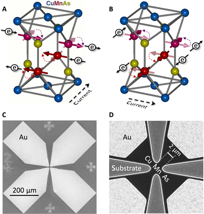
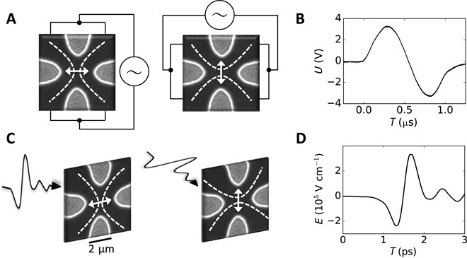
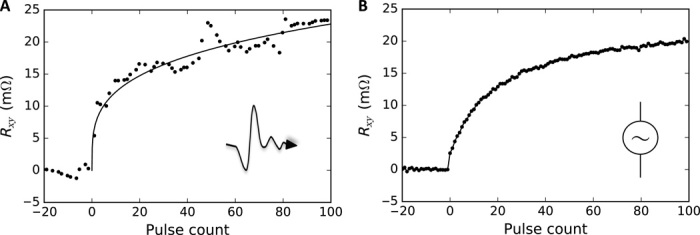
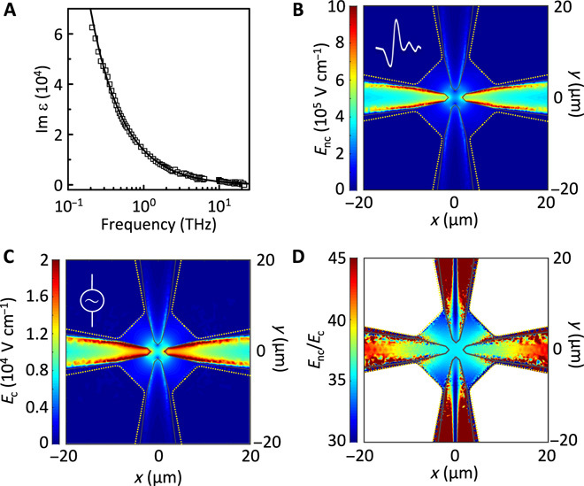
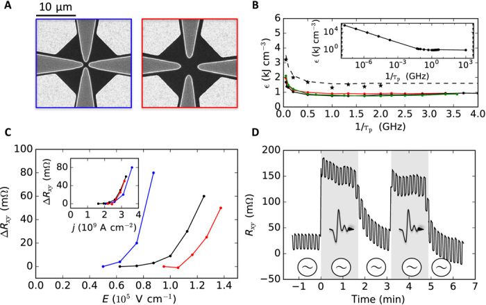
The speed of writing of state-of-the-art ferromagnetic memories is physically limited by an intrinsic gigahertz threshold. Recently, realization of memory devices based on antiferromagnets, in which spin directions periodically alternate from one atomic lattice site to the next has moved research in an alternative direction. We experimentally demonstrate at room temperature that the speed of reversible electrical writing in a memory device can be scaled up to terahertz using an antiferromagnet. A current-induced spin-torque mechanism is responsible for the switching in our memory devices throughout the 12-order-of-magnitude range of writing speeds from hertz to terahertz. Our work opens the path toward the development of memory-logic technology reaching the elusive terahertz band.


Figures

Fig. 1
Fig. 1. Switching principle and device images.
(A) Schematics of the crystal and magnetic structure of the CuMnAs antiferromagnet in which the two opposite magnetic sublattices occupy inversion partner Mn sites. A uniform electrical current (black dashed arrow) generates a nonequilibrium spin polarization of carriers (black electron symbols with spin arrows) with opposite sign at inversion partner Mn sites. The corresponding staggered effective magnetic field efficiently switches the antiferromagnetic moments (reorientation of thick red/purple arrows). (B) Reversible switching is achieved by applying the writing current in the orthogonal direction. (C) Electron microscopy image of the Au contact pads (light regions) of the device. (D) Detailed electron microscopy image of the device with a 2-μm-size central cross structure. Light regions are the apexes of Au contact pads, gray regions are etched down to the GaAs substrate, and black regions are CuMnAs.
Fig. 2
Fig. 2. Contact and noncontact experimental setup.
(A) Electron microscopy image of the cross-shape bit cell and schematics of the reversible writing by electrical pulses of two orthogonal current directions delivered via wire-bonded contacts. White dashed lines illustrate electrical current paths, and white double arrows show the corresponding preferred Néel vector orientations. (B) Waveform of the applied microsecond electrical pulses. (C) Schematics of the reversible writing by terahertz electric field transients whose linear polarization can be chosen along two orthogonal directions. (D) Waveform of the applied picosecond radiation pulses.
Fig. 3
Fig. 3. Comparison of switching by microsecond and picosecond pulses.
(A) Reversible multilevel switching by 30-s trains of microsecond electrical pulses with a hertz pulse repetition rate, delivered via wire-bonded contacts along two orthogonal directions. The applied writing current density in the 3.5-μm-size CuMnAs/GaAs cell is 3 × 10⁷ A cm–2. Intervals with the pulse trains turned on are highlighted in gray, and the two orthogonal current directions of the trains alternate from one interval to the next. Electrical readout is performed at a 1-Hz rate. Right insets show schematics of the transverse AMR readout. White dashed lines depict readout current paths. (B) Same as (A) for picosecond pulses with a kilohertz pulse repetition rate. The writing current density in the 2-μm-size CuMnAs/GaAs bit cell recalculated from the amplitude of the applied terahertz electric field transient is 2.7 × 10⁹ A cm–2. Electrical readout is performed at an 8-Hz rate.
Fig. 4
Fig. 4. Effects of individual picosecond and microsecond pulses.
(A) The multilevel memory signal as a function of the number of applied picosecond pulses. The writing current density in the 2-μm-size CuMnAs/GaAs bit cell recalculated from the applied terahertz field amplitude is 2.9 × 10⁹ A cm–2. (B) Same as (A) for the microsecond pulses and an applied writing current density of 3 × 10⁷ A cm–2 in the 3.5-μm-size CuMnAs/GaAs cell.
Fig. 5
Fig. 5. Electric field simulations in the device.
(A) Measured frequency-dependent imaginary part of the dielectric function (squares) and fitted expression Im ε = σ/ωε0 (line) with the dc conductivity σ = 8 × 10³ ohm− 1 cm− 1. (B) Numerical simulation of the electric field distribution in the device in the noncontact setup for a peak incident terahertz field of 105 V cm–1 polarized along the y axis. (C) Same as (B) in the contact setup for a voltage of 7 V applied between the top and bottom Au contacts. (D) Ratio of the electric fields in (B) and (C).
Fig. 6
Fig. 6. Switching energy calibration.
(A) Electron microscopy images of the 1- and 3-μm-size devices. Light regions are Au contact pads, gray regions are etched down to the GaAs substrate, and black regions are CuMnAs. (B) Magnitude of the switching signal as a function of the terahertz field amplitude (main panel) and of the converted current density (inset) for 1-, 2-, and 3-μm-size devices (blue, black, and red dots, respectively). (C) Writing energy density (black, red, and green dots), ϵ = j2τp/σ, required to obtain a 1-milliohm switching signal as a function of the writing speed 1/τp in the linear scale (main plot) and in the log-log scale (inset). All data points, except for the point at 1/τp= 1 THz in the inset, are obtained from the contact measurements. The point at 1/τp = 1 THz in the inset is from the noncontact measurement using the E to j conversion based on the breakdown energy (see text). Black dots in the main plot correspond to 2-μm-size, red to 3-μm-size, and green to 4-μm-size CuMnAs/GaAs bit cells. Black star symbols and dashed line represent the limiting breakdown energy density. (D) Contact writing by 200-ms pulses of current density 1 × 10⁷ A cm–2 (white intervals) and the contact writing superimposed on the noncontact writing by a train of picosecond pulses with a kilohertz repetition rate and a terahertz field amplitude corresponding to an additional current density of approximately 1.6 × 10⁹ A cm–2 (gray intervals). Data were measured in a 10-μm-size CuMnAs/Si bit cell.

References

    1. Chappert C., Fert A., Van Dau F. N., The emergence of spin electronics in data storage. Nat. Mater. 6, 813–823 (2007). - PubMed
    1. Brataas A., Kent A. D., Ohno H., Current-induced torques in magnetic materials. Nat. Mater. 11, 372–381 (2012). - PubMed
    1. Kent A. D., Worledge D. C., A new spin on magnetic memories. Nat. Nanotechnol. 10, 187–191 (2015). - PubMed
    1. Waldrop M. M., The chips are down for Moore’s law. Nature 530, 144–147 (2016). - PubMed
    1. Ralph D. C., Stiles M. D., Spin transfer torques. J. Magn. Magn. Mater. 320, 1190–1216 (2008).

Publication types

LinkOut - more resources