Review
. 2017 Dec 1;3(3):278-314.
doi: 10.1016/j.bioactmat.2017.10.001. eCollection 2018 Sep.

3D bioactive composite scaffolds for bone tissue engineering

Affiliations
Review

3D bioactive composite scaffolds for bone tissue engineering

Gareth Turnbull et al. Bioact Mater. .

Abstract

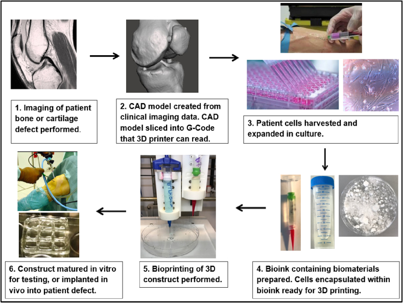
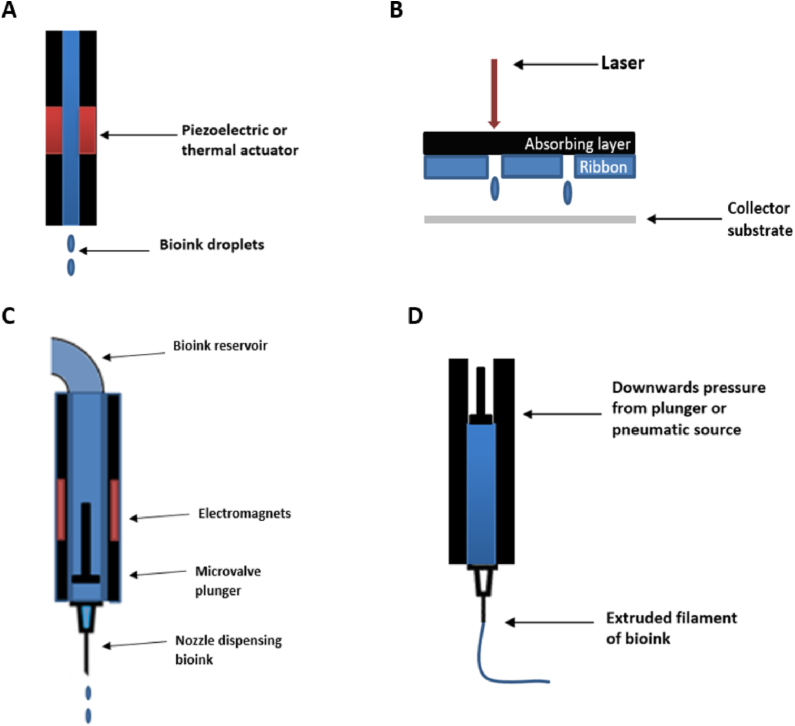
Bone is the second most commonly transplanted tissue worldwide, with over four million operations using bone grafts or bone substitute materials annually to treat bone defects. However, significant limitations affect current treatment options and clinical demand for bone grafts continues to rise due to conditions such as trauma, cancer, infection and arthritis. Developing bioactive three-dimensional (3D) scaffolds to support bone regeneration has therefore become a key area of focus within bone tissue engineering (BTE). A variety of materials and manufacturing methods including 3D printing have been used to create novel alternatives to traditional bone grafts. However, individual groups of materials including polymers, ceramics and hydrogels have been unable to fully replicate the properties of bone when used alone. Favourable material properties can be combined and bioactivity improved when groups of materials are used together in composite 3D scaffolds. This review will therefore consider the ideal properties of bioactive composite 3D scaffolds and examine recent use of polymers, hydrogels, metals, ceramics and bio-glasses in BTE. Scaffold fabrication methodology, mechanical performance, biocompatibility, bioactivity, and potential clinical translations will be discussed.

Keywords: 3D printing; 3D scaffold; Bioactive composites; Bioprinting; Bone; Tissue engineering.


Figures

Image 1
Graphical abstract
Fig. 1
Fig. 1
(A) SEM image showing interconnected porous structure of human trabecular bone (B) Pores and interconnecting pores demonstrated in hydroxyapatite scaffold. Pores are circled; arrows indicate interconnecting pores which allow communication between pores. Adapted from Doi et al. .
Fig. 2
Fig. 2
Common scaffold fabrication techniques. (A) Solvent casting-particle leaching process (B) Gas foaming (C) Freeze-drying (D) Phase separation (E) Electrospinning. Adapted from Puppi et al. .
Fig. 3
Fig. 3
Common 3D Printing Techniques. (A) Stereolithography (B) Fused deposition modelling (C) Selective laser sintering. Adapted from Jaster L .
Fig. 4
Fig. 4
Summary of bioprinting process.
Fig. 5
Fig. 5
Common bioprinting techniques: (A) Inkjet, (B) Laser-assisted, (C) Microvalve, and (D) Extrusion bioprinting.
Fig. 6
Fig. 6
SEM images of MC3T3 cells on the surface of 3D-printed Fe–Mg scaffold. White arrow denotes a cell–cell junction after one day; black arrows denote cellular extensions to pore walls after 3 days .
Fig. 7
Fig. 7
Photograph of injectable 3D-formed composite of β-TCP beads and alginate capable of triggering MSC osteogenic differentiation in vivo. (A) and light microscope photograph of the composite (B). SEM photographs of the composite (C) and surface of the composite (D). The composite was composed of β-TCP beads (∗) and alginate (#). Adapted from Matsuno et al. .
Fig. 8
Fig. 8
SEM images of (A) 10% and (B) 30% HA whiskers present in calcium silicate matrix. Adapted from Feng et al. .
Fig. 9
Fig. 9
Micro-CT and histomorphic analysis showing new bone formation in polymer-coated BG scaffolds implanted in mice for 8 weeks .
Fig. 10
Fig. 10
SEM images of the amine-coated MBG before (A) and after (B) soaking in SBF. Formation of a crystalline HA layer was confirmed on Fourier transform infrared spectroscopy .
Fig. 11
Fig. 11
Photograph of the biomimetic scaffold showing the external appearance and layered structure; SEM images showing the interface between scaffold layers .
Fig. 12
Fig. 12
Osteochondral scaffold, sized and press-fit into a patella defect. Adapted from Perdisa et al. .
Fig. 13
Fig. 13
Comparison of CS-ALs (10%)-implanted group to CS-ALs (0%) found significantly higher new bone formation, a finding which increased with time. SEM images of the CS-AL scaffold, with black arrows indicating the PLLA/nHA matrix and the white arrow indicating a CS/nHA-AL microspheres .
Fig. 14
Fig. 14
Micro-CT images of the artificial skull defects after 4 weeks, showing significant bone regeneration in HLA/HA-β-TCP composites (B) compared to control (A).
Fig. 15
Fig. 15
PCL/Alginate scaffold fabrication method. (A) 3D printing of micro-sized PCL struts (B) electrospinning of PCL/alginate onto PCL struts (C) punching process to create micro-sized pores in final PCL/alginate (PAS-S) scaffold. Adapted from Kim et al. .
Fig. 16
Fig. 16
(A) Photograph series showing the compression and recovery of a 1-cm-diameter 3D-printed HB cylinder over a single compression cycle (B) 12 × 12 cm sheet of HB printed from 100 ml HB ink, with ease of manipulation into complex folded structures shown (C) SEM image of explanted HB scaffold after 35 days in vivo; blood vessels indicated by yellow circles, with soft tissue filling space between HB fibres. Adapted from Jakus et al. .
Fig. 17
Fig. 17
(A) SEM micrographs of nHA/PLGA composite nanofiber scaffolds, with adherent cells after 24 h incubation also displayed (B).
Fig. 18
Fig. 18
(A) The 3D Discovery (Switzerland) bioprinter with microvalve print-head shown (B) 3D printed knee meniscus using NFC/A ink. Adapted from Markestedt et al. .
Fig. 19
Fig. 19
(A) Illustration of tissue manufacturing process (B) Photograph of a printed tissue construct housed within a perfusion chamber. Perfusion inlet and outlet seen at either end of tissue construct. Adapted from Kolesky et al. .
Fig. 20
Fig. 20
(A) PEGMC/HA composite being injected into collapsed femoral head; and (B)) Cross-sectional view of femoral head with injected composite visible. Crosslinking was achieved within 5 min of injection. Adapted from Jiao et al. .

References

    1. Kapferer R. 1938. Hippocrates, the Nature of Bones.
    1. Ashman O., Phillips A.M. Treatment of non-unions with bone defects: which option and why? Injury. 2013;44(Suppl 1):S43–S45. - PubMed
    1. Thaller P.H. Limb lengthening with fully implantable magnetically actuated mechanical nails (PHENIX((R)))-preliminary results. Injury. 2014;45(Suppl 1):S60–S65. - PubMed
    1. Greenwald A.S. Bone-graft substitutes: facts, fictions, and applications. J. Bone Jt. Surg. Am. 2001;83-A(Suppl 2 Pt 2):98–103. - PubMed
    1. Faour O. The use of bone graft substitutes in large cancellous voids: any specific needs? Injury. 2011;42(Suppl 2):S87–S90. - PubMed