. 2018 May 10;9(1):1860.
doi: 10.1038/s41467-018-04290-w.

Structural basis for cofilin binding and actin filament disassembly

Affiliations

Structural basis for cofilin binding and actin filament disassembly

Kotaro Tanaka et al. Nat Commun. .

Abstract

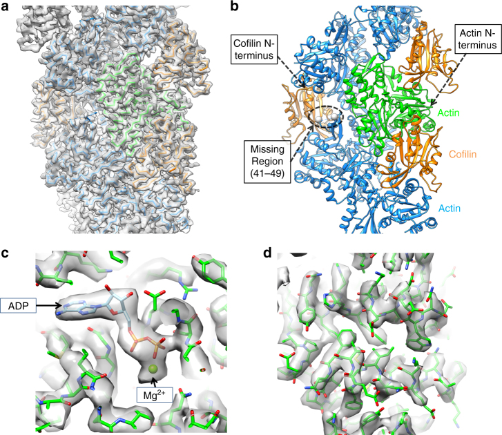
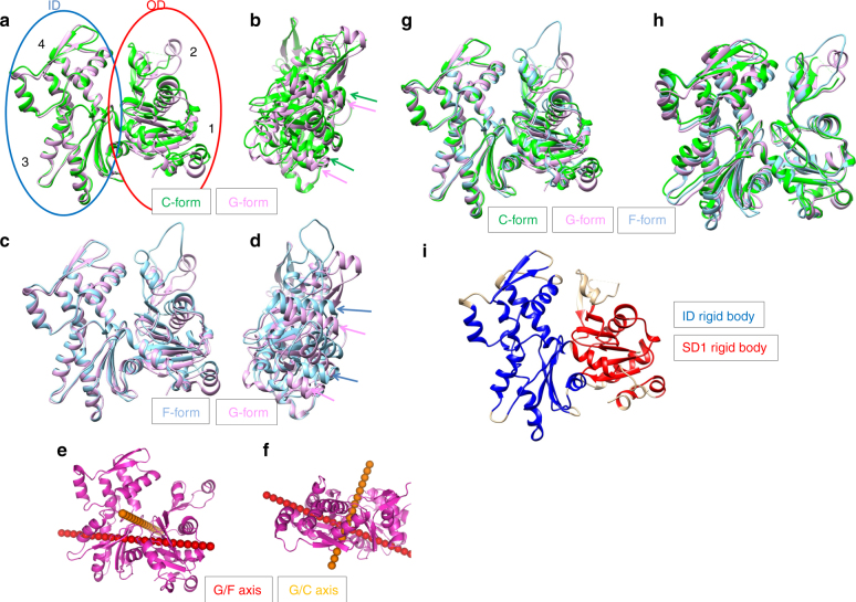
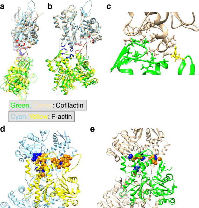
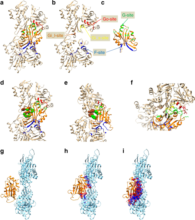
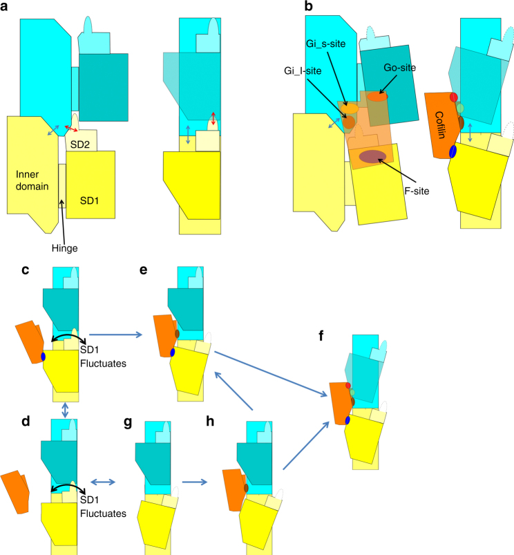
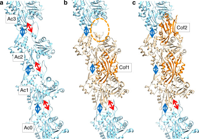
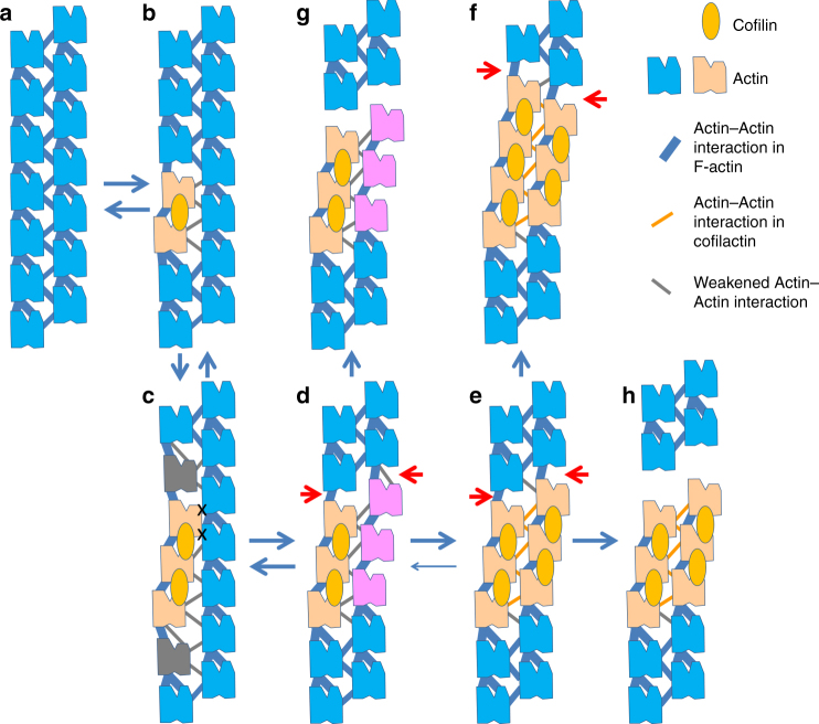
Actin depolymerizing factor (ADF) and cofilin accelerate actin dynamics by severing and disassembling actin filaments. Here, we present the 3.8 Å resolution cryo-EM structure of cofilactin (cofilin-decorated actin filament). The actin subunit structure of cofilactin (C-form) is distinct from those of F-actin (F-form) and monomeric actin (G-form). During the transition between these three conformations, the inner domain of actin (subdomains 3 and 4) and the majority of subdomain 1 move as two separate rigid bodies. The cofilin-actin interface consists of three distinct parts. Based on the rigid body movements of actin and the three cofilin-actin interfaces, we propose models for the cooperative binding of cofilin to actin, preferential binding of cofilin to ADP-bound actin filaments and cofilin-mediated severing of actin filaments.


Conflict of interest statement

The authors declare no competing interests.

Figures

Fig. 1
Fig. 1
Overall structure of cofilactin. a Cryo-EM map at a 3.8 Å resolution. The main chains of the cofilactin model are superimposed. One actin subunit, the other actin subunits and cofilins are presented in green, cyan and orange, respectively. The P-end is at the top. b Ribbon diagram of the cofilactin model with the same color scheme as in a. The viewing angle is also identical to a. The position of one missing region (41–49 of actin) is indicated by a dotted ellipse. Residues 40 and 50 of actin, the boundaries of the missing region, are presented by white spheres in the dotted ellipse. The N-termini of actin and cofilin, where some residues are missing, are indicated by arrows. c Cryo-EM map around ADP. The ADP and Mg2+ ions are indicated by arrows. d Cryo-EM map centered around actin residue 20
Fig. 2
Fig. 2
Actin structural changes in cofilactin. a Comparison between the G-actin (1J6Z, magenta, G-form) and actin subunit in cofilactin (green, C-form). The actin molecule is considered to have two domains, the inner domain (ID, blue ellipse) and outer domain (OD, red ellipse). Each domain is divided into two subdomains, OD into subdomains 1 and 2, and ID into 3 and 4. Each subdomain is indicated by a number (1, 2, 3 and 4). The structures are aligned through superimposition of the IDs. b Side view of a, rotated by 90°. Green and magenta arrows represent the orientation of two α-helices (79–95, 359–365) of the C-form and G-form, respectively. The two α-helices shift but do not tilt in the structural change. c Comparison between the G-form and F-form (5JLF, cyan). The structures are aligned through superimposition of the IDs. d Side view of c. Blue and magenta arrows represent the orientation of the two α-helices (79–95, 359–365) of the F-form and G-form, respectively. The two α-helices tilt in the structural change. e Rotation axes. G/F axis (red) and G/C axis (orange) are superposed on the G-form (1J6Z, magenta). f Top view of e. g The G-form (1J6Z, magenta), F-form (5JLF, cyan) and C-form (green) are superposed by aligning the rigid bodies of the ID (blue in Fig. 2i). h The three forms are superposed by aligning the rigid bodies of SD1 (red in Fig. 2i) as in G. i Rigid bodies in the ID and SD1 are shown in blue and red, respectively
Fig. 3
Fig. 3
Actin–actin interactions. The P-end is at the top. a Comparison of the intrastrand interactions between F-actin (5JLF, yellow and cyan) and cofilactin (green and camel). The structures are aligned through superimposition of the IDs. The residues that are found in the interface of both F-actin and cofilactin are colored blue, while those found solely in F-actin are colored red. b A 90° rotation of a. c An enlargement of the intrastrand interactions in cofilactin in the rectangle in b. The side chains on the interface are shown as a ball and stick model. Arg62, the only residue of the outer domain contributing to the intrastrand interactions, is presented in yellow. d Interstrand interactions of F-actin. The interface residues, whose side chains form the interface, are shown as a space-filling model. The interface residues of the yellow subunit are shown in orange, and the other residues are shown in blue. e Interstrand interactions of cofilactin. The interface residues in a space-filling model of the green subunit are shown in orange and the other residues are shown in blue
Fig. 4
Fig. 4
Actin–cofilin interactions. In ae and gi, the P-end is at the top. af Actin and cofilin are presented in camel and orange, respectively. The F-site (Cofilin-B-subunit interface), Go site (Cofilin-SD1 of the P-subunit interface), Gi_l site (Cofilin-ID of the P-subunit interface with long-range interactions) and Gi_s-sites (Cofilin-ID of the P-subunit interface which is not included in the Gi_l site) in the actin subunits are shown in blue, red, brown and yellow, respectively. In cofilin, residues forming the F-sites and G-sites are represented in blue and green, respectively. a Two actin subunits and the bound cofilin are presented. b Cofilin was removed from a. c Cofilin in a is rotated by 180°. d Residues contributing to the Gi_l-site are shown as a space-filling model. e A 50° rotation of d. f Residues within the Gi_s-sites and Go-sites are presented as sticks in an end-on view of the 111–119 helix of cofilin. gi Models showing the steric hindrance expected when cofilin binds to F-actin. Colliding atoms on both actin and cofilin are represented as a space-filling model in blue and red, respectively. The other atoms of the residues containing the colliding atoms are represented as a stick model. g A model of cofilin bound to the actin filament through the F-site. No collisions occur. h A model of cofilin bound through the Gi-site. i A model of cofilin bound through the Go-site
Fig. 5
Fig. 5
Schematic illustrations of intramolecular contacts. The P-end is at the top. Two actin subunits are shown (in yellow and cyan) from the longitudinal contact in one strand of the F-actin (a) and from the cofilactin filament (b). In a and b, the left panel is the front view and the right panel is the side view with the front surface on the left-hand side. In ch, each panel is a side view. a A schematic illustration of F-actin. Each actin molecule is in the F-form, where the ID and OD are aligned to be flat. The ID–ID and OD–ID interactions are represented by blue and red arrows, respectively. b A schematic illustration of the cofilactin filament. Cofilin is in orange. Actin and cofilin interact with each other through three interaction sites, the F-site (blue), Gi-site and Go-site (red). The Gi-site is subdivided into two parts, the Gi_l-site (brown) and Gi_s-site (yellow). Part of subdomain 2 (residues 41–49) is disordered and presented by dotted lines. The outer domain is tilted and the nucleotide-binding cleft is closed. The ID–ID interactions remain (blue arrow) while the OD–ID interactions diminish (Fig. 3a, b). ch Schematic illustrations of a multi-step model for cofilin binding to the actin filament. c, d Step 1. Cofilin binds to F-actin through the F-site (blue). The system at this stage is in equilibrium between the bound (c) and unbound (d) states. The OD of the ADP-bound actin subunit occasionally fluctuates (represented by the curved arrow). e Step 2. Cofilin bound through the F-site eventually approaches the Gi_l-site (brown), which is captured through binding of the flexible and extended side chains. f Step 3. The structural transition in the P-subunits is induced, and full G-site binding occurs (yellow and red). g, h An alternative pathway in which cofilin directly binds to F-actin through the Gi_l-site without F-site binding
Fig. 6
Fig. 6
Model for cooperative binding of cofilin to the actin filament. The P-end is at the top. a One strand of F-actin. The ID–ID and OD–ID intrastrand interactions are presented by blue and red arrows, respectively. b Model of one cofilin (Cof1) binding to Ac1 and Ac2. Ac1 and Ac2 are replaced by the cofilactin structure by aligning the inner domains of the actin subunits. Because of the structural transition of Ac2, the OD–ID interaction between Ac2 and Ac3 is eliminated, creating a space (orange ellipse) for Gi-site binding of another cofilin (Cof2). The form of each actin subunit, C-form or F-form, is indicated in camel and cyan, respectively. At the boundary of Ac1/Ac0, the ID–ID and OD–ID intrastrand interactions between the actin subunits (Fig. 5a, blue and red arrows, respectively) remain because there was no significant structural change inside the ID of Ac1 (C-form) from the F-form and because Ac0 is in the F-form. c Model of Cof2 binding to the Gi-site of Ac3 in b
Fig. 7
Fig. 7
Model for severing. The P-end is at the top. a F-actin. The F-form actin subunits are represented in blue. The intrastrand actin-actin contact is represented by a pair of thick blue lines, one for the ID–ID interactions and the other for the OD–ID interactions. The interstrand actin-actin contacts are also represented by thick blue lines. b Upon binding of the first cofilin molecule (orange oval) to one strand of the F-actin, two actin subunits undergo conformational transition into the C-form (camel), which is associated with a twist change in the actin strand, and therefore changes in relative positions of subunits. We assume that these positional changes weaken the interstrand contacts, as indicated by the thin gray lines. c The second cofilin binds next to the first cofilin on the same actin strand. Collision occurs between the strands, as indicated by an “X”. Accumulated position mismatches between actin subunits with and without bound cofilin may require adapter subunits at either boundary (gray). d As the size of the cofilin-bound section in the cofilin-bound strand increases, the helical twist transition propagates to the opposite strand. At this stage, the strain accumulated in the cofilin-bound strand and between the strands would be relieved. The cofilin-free actin subunits with the cofilactin helical twist are represented in magenta. The P-end boundary of the section is a candidate for severing (red arrows). e The helical twist change in the cofilin-free strand facilitates the binding of cofilin molecules to the strand, forming a double-stranded cofilin-bound cluster. The potential severing site remains (red arrows). Orange lines represent the interstrand interactions in cofilactin (Fig. 3e). f When another cofilin joins at the boundary of the cofilin cluster before severing, the cofilin cluster grows. The candidate severing site remains at the P-end boundary of the cluster (red arrowheads). g, h Severed filaments

References

    1. Kanellos G, Frame MC. Cellular functions of the ADF/cofilin family at a glance. J. Cell. Sci. 2016;129:3211–3218. doi: 10.1242/jcs.187849. - DOI - PubMed
    1. Bamburg JR, Harris HE, Weeds AG. Partial purification and characterization of an actin depolymerizing factor from brain. FEBS Lett. 1980;121:178–182. doi: 10.1016/0014-5793(80)81292-0. - DOI - PubMed
    1. Nishida E, Maekawa S, Sakai H. Cofilin, a protein in porcine brain that binds to actin filaments and inhibits their interactions with myosin and tropomyosin. Biochemistry. 1984;23:5307–5313. doi: 10.1021/bi00317a032. - DOI - PubMed
    1. Hild G, Kalmar L, Kardos R, Nyitrai M, Bugyi B. The other side of the coin: functional and structural versatility of ADF/cofilins. Eur. J. Cell. Biol. 2014;93:238–251. doi: 10.1016/j.ejcb.2013.12.001. - DOI - PubMed
    1. Ono S. Mechanism of depolymerization and severing of actin filaments and its significance in cytoskeletal dynamics. Int. Rev. Cytol. 2007;258:1–82. doi: 10.1016/S0074-7696(07)58001-0. - DOI - PubMed

Publication types

LinkOut - more resources