. 2017;3(1):14.
doi: 10.1186/s41205-017-0022-3. Epub 2017 Dec 6.

Preoperative planning and tracheal stent design in thoracic surgery: a primer for the 2017 Radiological Society of North America (RSNA) hands-on course in 3D printing

Affiliations

Preoperative planning and tracheal stent design in thoracic surgery: a primer for the 2017 Radiological Society of North America (RSNA) hands-on course in 3D printing

Leonid Chepelev et al. 3D Print Med. 2017.

Abstract

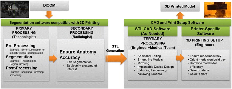
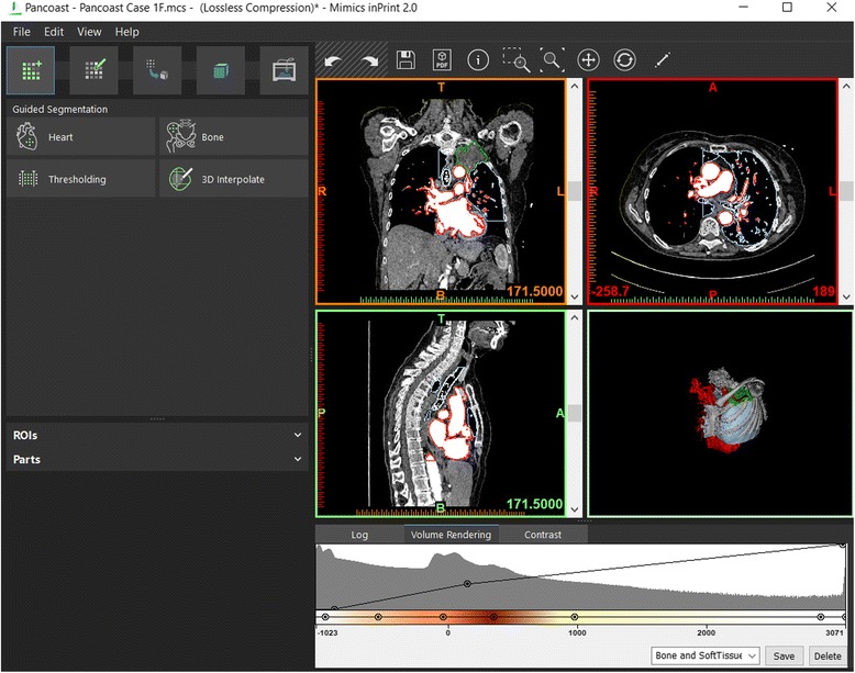
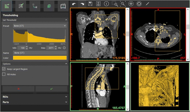
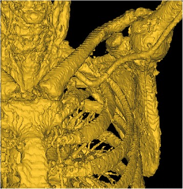
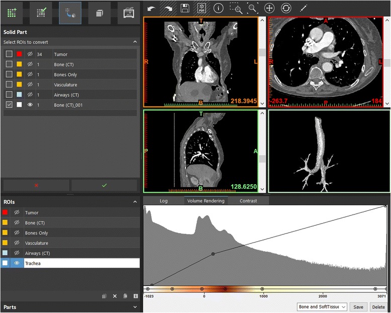
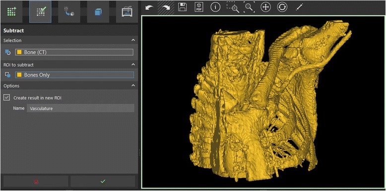
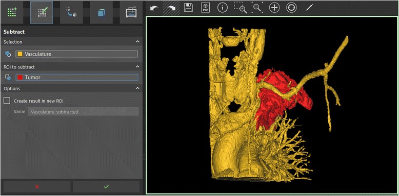
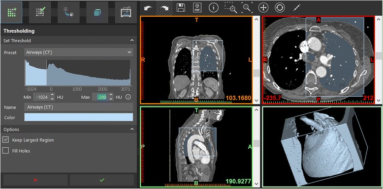
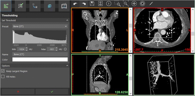
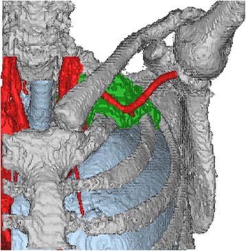
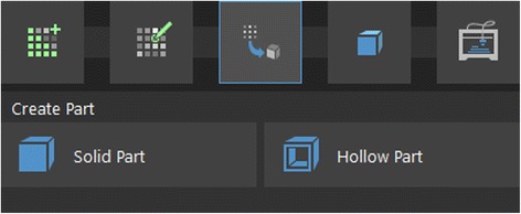
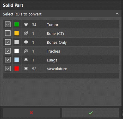
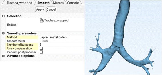
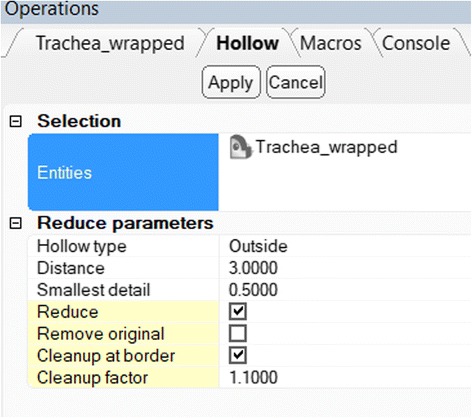
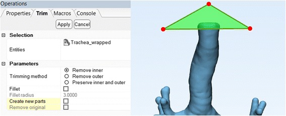
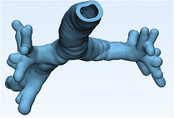
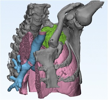
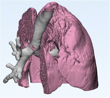
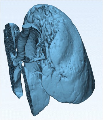
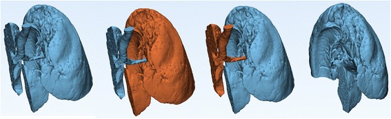
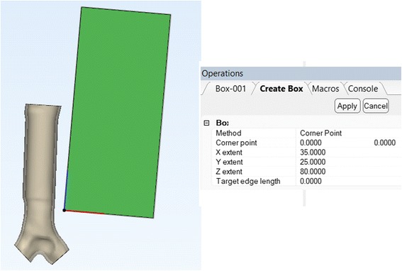
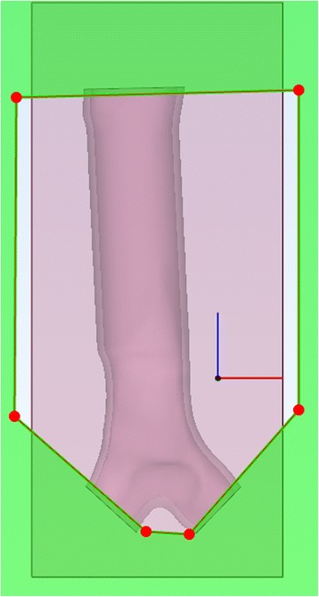
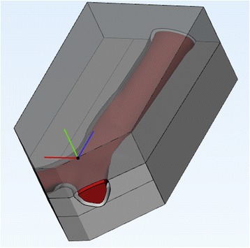
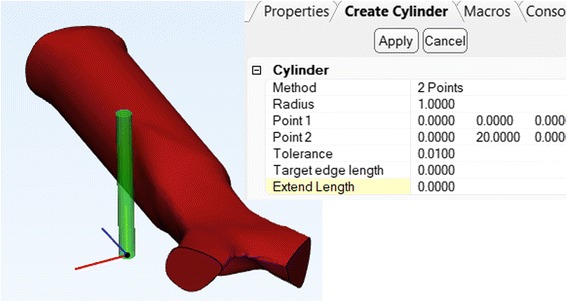
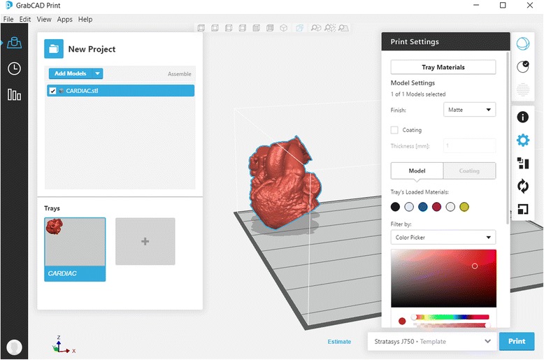
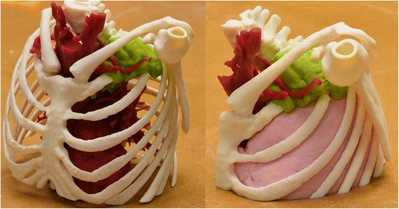
In this work, we provide specific clinical examples to demonstrate basic practical techniques involved in image segmentation, computer-aided design, and 3D printing. A step-by-step approach using United States Food and Drug Administration cleared software is provided to enhance surgical intervention in a patient with a complex superior sulcus tumor. Furthermore, patient-specific device creation is demonstrated using dedicated computer-aided design software. Relevant anatomy for these tasks is obtained from CT Digital Imaging and Communications in Medicine images, leading to the generation of 3D printable files and delivery of these files to a 3D printer.

Keywords: 3D printing; Cancer; Computer-aided design; Implant; Pancoast tumor; Precision medicine; Radiological Society of North America; Segmentation; Thoracic surgery; Tracheal Stenosis.


Conflict of interest statement

The authors declare that they have no competing interests.Springer Nature remains neutral with regard to jurisdictional claims in published maps and institutional affiliations.

Figures

Fig. 1
Fig. 1
General 3D Printing process overview, adapted from Mitsouras et al. [3]
Fig. 2
Fig. 2
Layout of the inPrint software graphical user interface. On the top left, the menu toolbar with File, Edit, View, and Help menus. Below this, menu toolbar with segmentation and model editing menus. The operation toolbar (titled Guided Segmentation on this view) contains the available operations and operation settings. Below this, the ROI and Part lists can be found. Top right, the three orthogonal planes and the 3D visualizations are shown. Finally, the lower right is reserved for software logs and various HU distribution and window/level visualizations
Fig. 3
Fig. 3
Setting up the segmentation for osseous structures
Fig. 4
Fig. 4
Result of the segmentation operation with HU, contiguity, and bounding box restrictions
Fig. 5
Fig. 5
Setting up the splitting tool and marking up the appropriate osseous anatomy as the foreground (blue) and vascular anatomy as background (black). Note image 292 is not shown
Fig. 6
Fig. 6
Results of the Split tool, separating the majority of the osseous structures from the vasculature
Fig. 7
Fig. 7
Using the Brush tool to erase unwanted portions of the ROI, slice-by-slice
Fig. 8
Fig. 8
Split tool in action – left clicking on the desired contiguous portion of the anatomy isolates it (green) from the non-contiguous fragments (yellow)
Fig. 9
Fig. 9
Renaming, showing/hiding, and recoloring ROIs
Fig. 10
Fig. 10
Setting up ROI subtraction
Fig. 11
Fig. 11
Second application of the ROI subtraction tool.
Fig. 12
Fig. 12
Segmenting the airways using the Airways (CT) preset
Fig. 13
Fig. 13
Segmentation of the trachea. Note the HU range and the narrow bounding box adjustments
Fig. 14
Fig. 14
Results of the segmentation
Fig. 15
Fig. 15
Selection of the Solid Part function from the ‘Create Part’ menu (highlighted)
Fig. 16
Fig. 16
Selection of the ROIs to convert to 3D models
Fig. 17
Fig. 17
Setup of the Export operation
Fig. 18
Fig. 18
Graphical user interface of the 3-matic software. Top left, the menu and tabbed menu toolbars. Center, work area with the visualization of the current model. Right upper corner, the Object Tree with all the involved objects. Right lower corner, the Operations tab, with all operation parameters. Bottom left, the Logger which logs the current actions. Note the Expert Mode at the bottom of the window. This expert mode allows control of additional parameters, some of which are used in this work
Fig. 19
Fig. 19
Setting up the Wrap operation for the trachea.
Fig. 20
Fig. 20
The smoothed and wrapped tracheal model (blue) overlapped with the original model (grey)
Fig. 21
Fig. 21
Setup of the smoothing operation. Note the yellow settings, which are the advanced settings that can be turned on or off using the Expert Mode toggle at the bottom of the window
Fig. 22
Fig. 22
Setting up the hollow operation
Fig. 23
Fig. 23
Setting up the Trim operation
Fig. 24
Fig. 24
Hollow model of the trachea.
Fig. 25
Fig. 25
Sample output of the wrapping and smoothing operations on the model elements. Individual results may vary based on the selected parameters
Fig. 26
Fig. 26
Models of the trachea and the lung. Note the significant overlap
Fig. 27
Fig. 27
Lung model following subtraction of the hollow trachea.
Fig. 28
Fig. 28
Selecting the non-contiguous portions of the lung models and deleting them
Fig. 29
Fig. 29
Tracheal model with simulated mass effect
Fig. 30
Fig. 30
Create Cylinder operation. Note, you may need to find the origin within the Work Area to see the new cylinder
Fig. 31
Fig. 31
Interactive rotation and translation, achieved by dragging corresponding arcs or axes in the model-associated orthogonal planes
Fig. 32
Fig. 32
Boolean Union operation to create the first approximation of the stent prototype
Fig. 33
Fig. 33
Setup and the result of the Wrap operation (blue) with a -1 mm offset in relation to the original Boolean Union result (grey, transparent)
Fig. 34
Fig. 34
Setup and result of the Hollow operation
Fig. 35
Fig. 35
Setting up the trimming operation to create a hollow stent
Fig. 36
Fig. 36
Final stent (blue) inside the original airway model (red), demonstrating adherence to the lumen
Fig. 37
Fig. 37
Setup for the Create Box operation
Fig. 38
Fig. 38
Using the trimming function on the result of subtraction of the stent from the box primitive
Fig. 39
Fig. 39
The result of separation of inner and outer portions and trimming the outer portion
Fig. 40
Fig. 40
Setup for the Create Cylinder operation
Fig. 41
Fig. 41
Trimming the support pins (left), using the Boolean union operation on the pins and the appropriate outer mold part (center), with the final result demonstrated (right)
Fig. 42
Fig. 42
Final mold assembled (left) and with the upper part demonstrated separately. Note the support pins, which can be of variable diameter
Fig. 43
Fig. 43
GrabCAD graphical user interface, with visualization of the printable 3D model on a dynamically rotatable tray that adheres to the dimensions of the selected printer. Associated print settings allow the selection of materials for individual models, as well as model placement and cost estimation
Fig. 44
Fig. 44
Results of dynamic cost estimates within the GrabCAD software. Typically, several printing options are provided -here, High Quality has a 14 μm resolution while High Mix results in 27 μm resolution prints
Fig. 45
Fig. 45
Left, a model of the entire bony and vascular thorax from the case presented here. Right, the left upper thorax segmented and further processed in this work. The tumor is shown in green, and closely abuts but does not involve the adjacent arterial vasculature

References

    1. Giannopoulos AA, Chepelev LL, Sheikh A, Wang A, Dang W, Akyuz E, Hong C, Wake N, Pietila P, Dydynski PB, Mitsouras D, Rybicki FJ. 3D printed ventricular Septal defect patch: a primer for the 2015 Radiological Society of North America (RSNA) hands-on course in 3D printing. 3D Printing in Medicine. 2015;1:3. doi: 10.1186/s41205-015-0002-4. - DOI - PMC - PubMed
    1. Chepelev LL, Hodgdon T, Gupta A, Wang A, Torres C, Krishna S, Akyuz E, Mitsouras D. Medical 3D printing for vascular interventions and surgical oncology: a primer for the 2016 Radiological Society of North America (RSNA) hands-on course in 3D printing. 3D Printing in Medicine. 2016;2:5. doi: 10.1186/s41205-016-0008-6. - DOI - PMC - PubMed
    1. Mitsouras D, Liacouras P, Imanzadeh A, Giannopoulos AA, Cai T, Kumamaru KK, George E, Wake N, Caterson EJ, Pomahac B, Ho VB, Grant GT, Rybicki FJ. Medical 3D printing for the radiologist. Radiographics. 2015;35:1965–1988. doi: 10.1148/rg.2015140320. - DOI - PMC - PubMed
    1. Chepelev L, Giannopoulos A, Tang A, Mitsouras D, Rybicki FJ. Medical 3D printing: methods to standardize terminology and report trends. 3D Printing in Medicine. 2017;3:4. doi: 10.1186/s41205-017-0012-5. - DOI - PMC - PubMed
    1. George E, Barile M, Tang A, Wiesel O, Coppolino A, Giannopoulos A, Mentzer S, Jaklitsch M, Hunsaker A, Mitsouras D. Utility and reproducibility of 3-dimensional printed models in pre-operative planning of complex thoracic tumors. J Surg Oncol. 2017;116:407–415. doi: 10.1002/jso.24684. - DOI - PMC - PubMed