

Enabling Angioplasty-Ready "Smart" Stents to Detect In-Stent Restenosis and Occlusion
- PMID: 29876203
- PMCID: PMC5979749
- DOI: 10.1002/advs.201700560
Enabling Angioplasty-Ready "Smart" Stents to Detect In-Stent Restenosis and Occlusion
Abstract
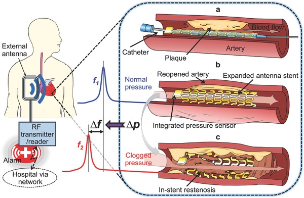
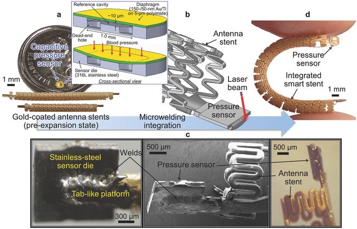
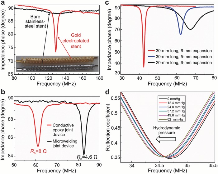
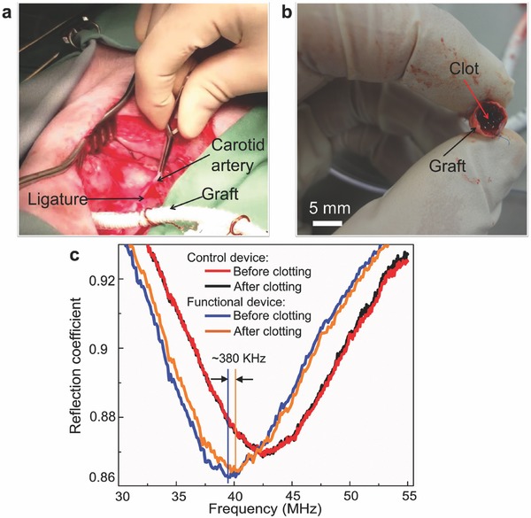
Despite the multitude of stents implanted annually worldwide, the most common complication called in-stent restenosis still poses a significant risk to patients. Here, a "smart" stent equipped with microscale sensors and wireless interface is developed to enable continuous monitoring of restenosis through the implanted stent. This electrically active stent functions as a radiofrequency wireless pressure transducer to track local hemodynamic changes upon a renarrowing condition. The smart stent is devised and constructed to fulfill both engineering and clinical requirements while proving its compatibility with the standard angioplasty procedure. Prototypes pass testing through assembly on balloon catheters withstanding crimping forces of >100 N and balloon expansion pressure up to 16 atm, and show wireless sensing with a resolution of 12.4 mmHg. In a swine model, this device demonstrates wireless detection of blood clot formation, as well as real-time tracking of local blood pressure change over a range of 108 mmHg that well covers the range involved in human. The demonstrated results are expected to greatly advance smart stent technology toward its clinical practice.
Keywords: angioplasty; restenosis; smart medical implants; stents; wireless sensing.
Figures


Similar articles
-
Intelligent telemetric stent for wireless monitoring of intravascular pressure and its in vivo testing.Biomed Microdevices. 2014 Oct;16(5):745-59. doi: 10.1007/s10544-014-9879-8. Biomed Microdevices. 2014. PMID: 24903011
-
Wirelessly Heating Stents via Radiofrequency Resonance toward Enabling Endovascular Hyperthermia.Adv Healthc Mater. 2019 Nov;8(22):e1900708. doi: 10.1002/adhm.201900708. Epub 2019 Oct 18. Adv Healthc Mater. 2019. PMID: 31625695
-
Intelligent Ureteral Stent Placeable via Standard Procedure for Kidney Pressure Telemetry: An Ex-Vivo Study.Ann Biomed Eng. 2025 Jan;53(1):180-192. doi: 10.1007/s10439-024-03610-0. Epub 2024 Sep 24. Ann Biomed Eng. 2025. PMID: 39316307
-
[Pathophysiology and therapeutic concepts in coronary restenosis].Herz. 1997 Dec;22(6):322-34. doi: 10.1007/BF03044283. Herz. 1997. PMID: 9483438 Review. German.
-
[Balloon angioplasty of stent restenosis: early and late results of first and second PTCA in focal and diffuse stenosis].Z Kardiol. 1998;87 Suppl 3:65-71; discussion 79-80. doi: 10.1007/s003920050541. Z Kardiol. 1998. PMID: 9791913 Review. German.
Cited by
-
Health Care Monitoring and Treatment for Coronary Artery Diseases: Challenges and Issues.Sensors (Basel). 2020 Aug 1;20(15):4303. doi: 10.3390/s20154303. Sensors (Basel). 2020. PMID: 32752231 Free PMC article. Review.
-
Structural Design of Vascular Stents: A Review.Micromachines (Basel). 2021 Jun 29;12(7):770. doi: 10.3390/mi12070770. Micromachines (Basel). 2021. PMID: 34210099 Free PMC article. Review.
-
The Future of Cardiovascular Stents: Bioresorbable and Integrated Biosensor Technology.Adv Sci (Weinh). 2019 Aug 19;6(20):1900856. doi: 10.1002/advs.201900856. eCollection 2019 Oct 16. Adv Sci (Weinh). 2019. PMID: 31637160 Free PMC article. Review.
-
Machine Learning-Enhanced Flexible Mechanical Sensing.Nanomicro Lett. 2023 Feb 17;15(1):55. doi: 10.1007/s40820-023-01013-9. Nanomicro Lett. 2023. PMID: 36800133 Free PMC article. Review.
-
Current state of the art and future directions for implantable sensors in medical technology: Clinical needs and engineering challenges.APL Bioeng. 2023 Sep 27;7(3):031506. doi: 10.1063/5.0152290. eCollection 2023 Sep. APL Bioeng. 2023. PMID: 37781727 Free PMC article. Review.
References
-
- Santulli G., J. Cardiovasc. Dis. 2013, 1, 1.
-
- Rauch U., Osende J. I., Fuster V., Badimon J. J., Fayad Z., Chesebro J. H., Ann. Intern. Med. 2001, 134, 224. - PubMed
-
- Serruys P. W., Jaegere P. D., Kiemeneij F., Macaya C., Rutsch W., Heyndrickx G., Emanuelsson H., Marco J., Legrand V., Materne P., Belardi J., Sigwart U., Colombo A., Goy J. J., Heuvel P. V. D., Delcan J., Morel M. A., N. Engl. J. Med. 1994, 331, 489. - PubMed
-
- Kornowski R., Hong M. K., Tio F. O., Bramwell O., Wu H., Leon M. B., J. Am. Coll. Cardiol. 1998, 31, 224. - PubMed
-
- Lowe H. C., Oesterle S. N., Khachigian L. M., J. Am. Coll. Cardiol. 2002, 39, 183. - PubMed
LinkOut - more resources
Full Text Sources
Other Literature Sources
Research Materials
Miscellaneous