

Organic/Inorganic Metal Halide Perovskite Optoelectronic Devices beyond Solar Cells
- PMID: 29876207
- PMCID: PMC5980182
- DOI: 10.1002/advs.201700780
Organic/Inorganic Metal Halide Perovskite Optoelectronic Devices beyond Solar Cells
Abstract
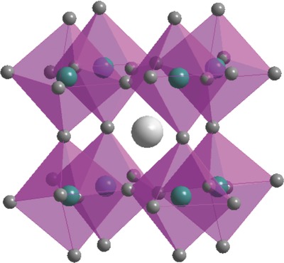
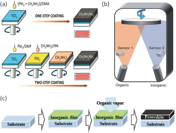
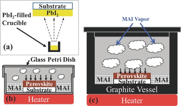
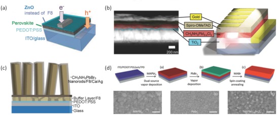
Investigations of organic-inorganic metal halide perovskite materials have attracted extensive attention due to their excellent properties including bandgap tunability, long charge diffusion length, and outstanding optoelectronic merits. Organic-inorganic metal halide perovskites are demonstrated to be promising materials in a variety of optoelectronic applications including photodetection, energy harvesting, and light-emitting devices. As perovskite solar cells are well studied in literature, here, the recent developments of organic-inorganic metal halide perovskite materials in optoelectronic devices beyond solar cells are summarized. The preparation of organic-inorganic metal halide perovskite films is introduced. Applications of organic-inorganic metal halide perovskite materials in light-emitting diodes, photodetectors, and lasers are then highlighted. Finally, the recent advances in these optoelectronic applications based on organic-inorganic metal halide materials are summarized and the future perspectives are discussed.
Keywords: lasers; light emitting diodes; organic/inorganic hybrid perovskites; photodetectors.
Figures
Similar articles
-
Highly Stable Inorganic Lead Halide Perovskite toward Efficient Photovoltaics.Acc Chem Res. 2021 Sep 7;54(17):3452-3461. doi: 10.1021/acs.accounts.1c00343. Epub 2021 Aug 24. Acc Chem Res. 2021. PMID: 34428021
-
Two-Dimensional Materials for Halide Perovskite-Based Optoelectronic Devices.Adv Mater. 2017 Jun;29(24). doi: 10.1002/adma.201605448. Epub 2017 Mar 3. Adv Mater. 2017. PMID: 28256781 Review.
-
Advances in the Application of Perovskite Materials.Nanomicro Lett. 2023 Jul 10;15(1):177. doi: 10.1007/s40820-023-01140-3. Nanomicro Lett. 2023. PMID: 37428261 Free PMC article. Review.
-
Halide perovskite single crystals: growth, characterization, and stability for optoelectronic applications.Nanoscale. 2022 Jul 7;14(26):9248-9277. doi: 10.1039/d2nr00513a. Nanoscale. 2022. PMID: 35758131 Review.
-
Thermally Evaporated Metal Halide Perovskites and Their Analogues: Film Fabrication, Applications and Beyond.Small Methods. 2025 Feb;9(2):e2301633. doi: 10.1002/smtd.202301633. Epub 2024 Apr 29. Small Methods. 2025. PMID: 38682581 Free PMC article. Review.
Cited by
-
Pressure-induced polymerization and bandgap-adjustment of TPEPA.RSC Adv. 2022 Apr 19;12(19):11996-12001. doi: 10.1039/d2ra01144a. eCollection 2022 Apr 13. RSC Adv. 2022. PMID: 35481090 Free PMC article.
-
Phase Behavior and Role of Organic Additives for Self-Doped CsPbI3 Perovskite Semiconductor Thin Films.Micromachines (Basel). 2023 Aug 14;14(8):1601. doi: 10.3390/mi14081601. Micromachines (Basel). 2023. PMID: 37630137 Free PMC article.
-
Position Effects of Metal Nanoparticles on the Performance of Perovskite Light-Emitting Diodes.Nanomaterials (Basel). 2021 Apr 13;11(4):993. doi: 10.3390/nano11040993. Nanomaterials (Basel). 2021. PMID: 33924555 Free PMC article.
-
All-Perovskite Photodetector with Fast Response.Nanoscale Res Lett. 2019 Aug 22;14(1):291. doi: 10.1186/s11671-019-3082-z. Nanoscale Res Lett. 2019. PMID: 31441017 Free PMC article.
-
Charge Carriers Are Not Affected by the Relatively Slow-Rotating Methylammonium Cations in Lead Halide Perovskite Thin Films.J Phys Chem Lett. 2019 Sep 5;10(17):5128-5134. doi: 10.1021/acs.jpclett.9b02160. Epub 2019 Aug 21. J Phys Chem Lett. 2019. PMID: 31398042 Free PMC article.
References
-
- Zhu Z.‐Y., Yang Q.‐Q., Gao L.‐F., Zhang L., Shi A.‐Y., Sun C.‐L., Wang Q., Zhang H.‐L., J. Phys. Chem. Lett. 2017, 8, 1610. - PubMed
-
- Hirasawa M., Ishihara T., Goto T., Sasaki S., Uchida K., Miura N., Soild State Commun. 1993, 86, 479.
-
- Mitzi D., Chem. Mater. 1996, 8, 791.
-
- Kammoun S., Kamoun M., Daoud A., Lautie A., J. Phys.: Condens. Matter 1996, 8, 8465.
-
- Kitazawa N., Mater. Sci. Eng., B 1997, 49, 233.
Publication types
LinkOut - more resources
Full Text Sources
Other Literature Sources
Research Materials