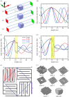
Predicting double negativity using transmitted phase in space coiling metamaterials
- PMID: 29892344
- PMCID: PMC5990839
- DOI: 10.1098/rsos.171042
Predicting double negativity using transmitted phase in space coiling metamaterials
Abstract
Metamaterials are engineered materials that offer the flexibility to manipulate the incident waves leading to exotic applications such as cloaking, extraordinary transmission, sub-wavelength imaging and negative refraction. These concepts have largely been explored in the context of electromagnetic waves. Acoustic metamaterials, similar to their optical counterparts, demonstrate anomalous effective elastic properties. Recent developments have shown that coiling up the propagation path of acoustic wave results in effective elastic response of the metamaterial beyond the natural response of its constituent materials. The effective response of metamaterials is generally evaluated using the 'S' parameter retrieval method based on amplitude of the waves. The phase of acoustic waves contains information of wave pressure and particle velocity. Here, we show using finite-element methods that phase reversal of transmitted waves may be used to predict extreme acoustic properties in space coiling metamaterials. This change is the difference in the phase of the transmitted wave with respect to the incident wave. This method is simpler when compared with the more rigorous 'S' parameter retrieval method. The inferences drawn using this method have been verified experimentally for labyrinthine metamaterials by showing negative refraction for the predicted band of frequencies.
Keywords: acoustics; metamaterials; negative refractive index.
Conflict of interest statement
We declare we have no competing interests.
Figures


References
-
- Li J, Fork L, Yin X, Bartal G, Zhang X. 2009. Experimental demonstration of an acoustic magnifying hyperlens. Nat. Mater. 8, 931–934. (doi:10.1038/nmat2561) - DOI - PubMed
-
- Zhang X, Liu Z. 2004. Negative refraction of acoustic waves in two-dimensional phononic crystals. Appl. Phys. Lett. 85, 341 (doi:10.1063/1.1772854) - DOI
-
- Zhang S, Yin L, Fang N. 2009. Focusing ultrasound with an acoustic metamaterial network. Phys. Rev. Lett. 102, 194301 (doi:10.1103/PhysRevLett.102.194301) - DOI - PubMed
-
- Zhu J, Christensen J, Jung J, Martin-Moreno L, Yin X, Fok L, Zhang X, Garcia-Vidal FJ. 2011. A holey-structured metamaterial for acoustic deep-subwavelength imaging. Nat. Phys. 7, 52–55. (doi:10.1038/nphys1804) - DOI
-
- Lemoult F, Kaina N, Fink M, Lerosey G. 2012. Wave propagation control at the deep subwavelength scale in metamaterials. Nat. Phys. 9, 55 (doi:10.1038/nphys2480) - DOI
Associated data
LinkOut - more resources
Full Text Sources
Other Literature Sources
