Review
. 2018 Aug;27(8):1364-1391.
doi: 10.1002/pro.3445. Epub 2018 Jul 10.

Mechanism of neurotransmitter release coming into focus

Affiliations
Review

Mechanism of neurotransmitter release coming into focus

Josep Rizo. Protein Sci. 2018 Aug.

Abstract

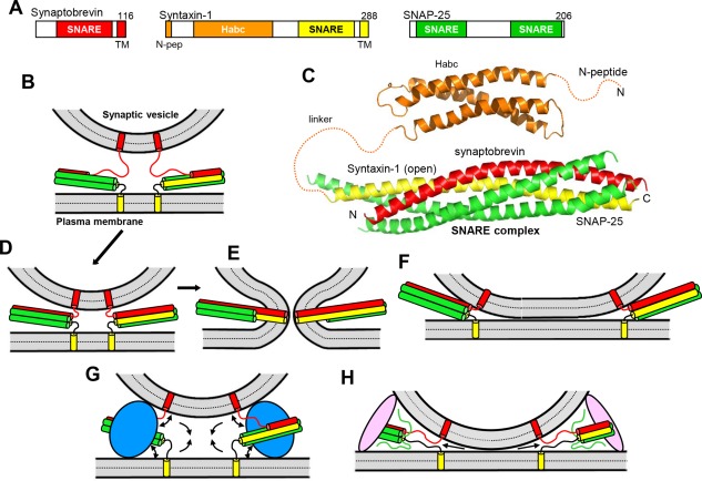
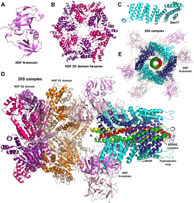
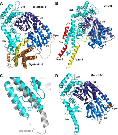
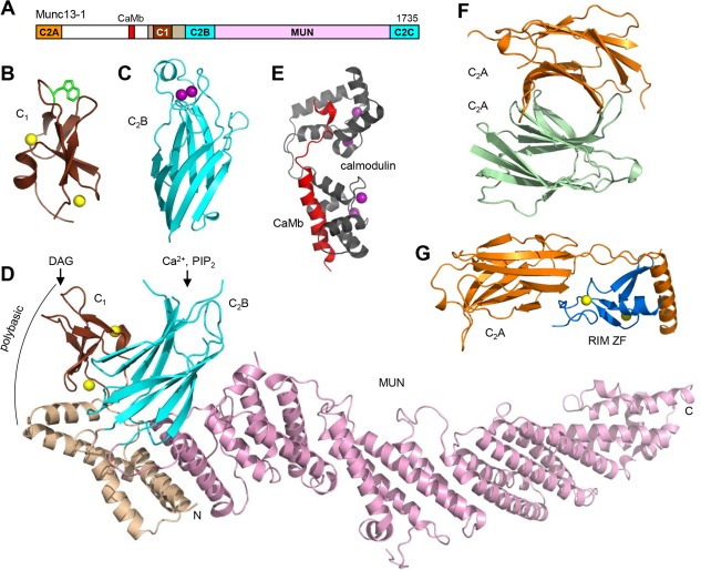
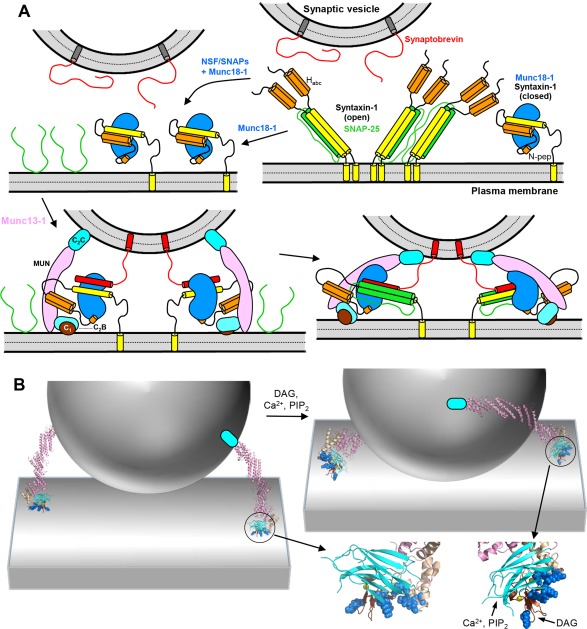
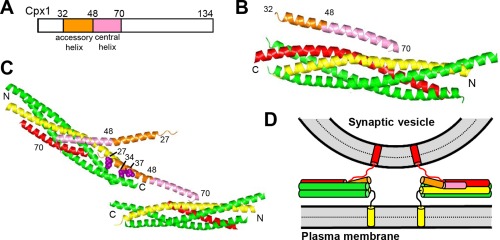
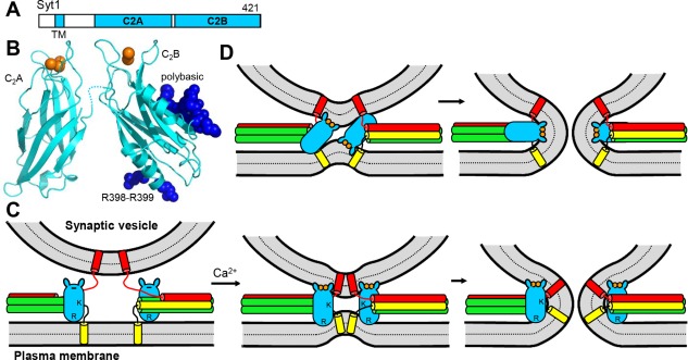
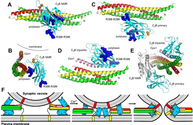
Research for three decades and major recent advances have provided crucial insights into how neurotransmitters are released by Ca2+ -triggered synaptic vesicle exocytosis, leading to reconstitution of basic steps that underlie Ca2+ -dependent membrane fusion and yielding a model that assigns defined functions for central components of the release machinery. The soluble N-ethyl maleimide sensitive factor attachment protein receptors (SNAREs) syntaxin-1, SNAP-25, and synaptobrevin-2 form a tight SNARE complex that brings the vesicle and plasma membranes together and is key for membrane fusion. N-ethyl maleimide sensitive factor (NSF) and soluble NSF attachment proteins (SNAPs) disassemble the SNARE complex to recycle the SNAREs for another round of fusion. Munc18-1 and Munc13-1 orchestrate SNARE complex formation in an NSF-SNAP-resistant manner by a mechanism whereby Munc18-1 binds to synaptobrevin and to a self-inhibited "closed" conformation of syntaxin-1, thus forming a template to assemble the SNARE complex, and Munc13-1 facilitates assembly by bridging the vesicle and plasma membranes and catalyzing opening of syntaxin-1. Synaptotagmin-1 functions as the major Ca2+ sensor that triggers release by binding to membrane phospholipids and to the SNAREs, in a tight interplay with complexins that accelerates membrane fusion. Many of these proteins act as both inhibitors and activators of exocytosis, which is critical for the exquisite regulation of neurotransmitter release. It is still unclear how the actions of these various proteins and multiple other components that control release are integrated and, in particular, how they induce membrane fusion, but it can be expected that these fundamental questions can be answered in the near future, building on the extensive knowledge already available.

Keywords: Munc13; Munc18; NSF; SNAPs; SNAREs; complexin; neurotransmitter release; synaptic vesicle fusion; synaptotagmin.


Figures

Figure 1
Figure 1
Models of SNARE‐dependent membrane fusion. (A) Domain structures of synaptobrevin, syntaxin‐1 and SNAP‐25. SNARE indicates SNARE motif and N‐pep indicates the N‐peptide of syntaxin‐1. Numbers on the right above the diagrams indicate the length of the protein. The same color coding for the SNAREs is used in all figures. (B) Diagram illustrating the topology of the neuronal SNAREs, with synaptobrevin anchored on a synaptic vesicle and syntaxin‐1 anchored on the plasma membrane, and showing how the SNAREs can form partially assembled trans‐SNARE complexes between the two membranes. In this model, the N‐terminal half of the four‐helix bundle is assembled and the C‐terminal half of the synaptobrevin SNARE motif is unstructured; the syntaxin‐1 and SNAP‐25 SNARE motifs are often assumed to be fully helical, as shown in the diagram, but their C‐termini may actually be unstructured.164 (C) Ribbon diagrams representing the three‐dimensional structures of the syntaxin‐1 H abc domain19 (PDB accession code 1BR0) and the neuronal SNARE complex12 (PDB accession code 1SFC). N and C indicate the N‐ and C‐terminus, respectively. Dashed curves represent flexible regions that were not present in the elucidated structures. (D–E) Together with panel (B), these diagrams illustrate the widespread model whereby the SNARE complex is initially formed at the N‐terminus (B), it zippers toward the C‐terminus, bringing the two membranes in close proximity (D), and causes membrane fusion as continuous helices are formed by the SNARE motifs and TM regions of syntaxin‐1 and synaptobrevin, as well as the short linkers between them.12, 27, 38 (E). For simplicity, only the SNARE motifs, TM regions and these short linkers are shown. (F) Diagram showing how SNARE complex assembly can lead to extended membrane‐membrane interfaces without fusion.32 (G) Diagram illustrating how a bulky protein(s) (blue) bound to the SNARE four‐helix bundle could play a key role in membrane fusion by pushing the membranes away from each other at the same time that assembly of the SNARE complex pulls the membranes together, which could cause a torque (see arrows) that helps to bend the membranes and initiate fusion.45, 46 (H) Diagram showing how membrane bridging by an elongated tethering factor (pink) could bring the vesicle and plasma membranes into proximity. In this arrangement, the SNARE complex would assemble in the periphery of the membrane‐membrane interface, perhaps bound to the bridging protein and/or another factor, and C‐terminal zippering of the SNARE complex could pull the membranes radially (see arrows), thus perturbing the packing of the lipids and catalyzing membrane fusion.48
Figure 2
Figure 2
Structures of NSF, SNAP/Sec17 and the 20S complex. (A–E) Ribbon diagrams showing the three‐dimensional structures of the N‐terminal domain of NSF51 (A), the NSF D2 domain hexamer53 (B), Sec1755 (C), and the 20S complex56 (D,E). The PDB accession codes are 1QDN, 1NSF, 1QQE, and 3J96, respectively. In (C) and (D), N and C indicate the N‐ and C‐termini of Sec17 (C) and the SNARE four‐helix bundle (D), respectively. Panels (D,E) show two different views of the 20S complex rotated approximately 90°. In (E), the C‐terminus of the SNARE four‐helix bundle is pointing to the front. For alternate subunits of NSF, the N‐terminal domain is shown in violet or light pink, the D1 domain in orange or wheat, and the D2 domain in magenta or purple. Alternate αSNAP subunits are shown in cyan or deep blue. The N‐terminal hydrophobic loop of one of the αSNAP subunits is indicated in (D).
Figure 3
Figure 3
Structures of SM protein‐SNARE complexes. (A) Ribbon diagram showing the three‐dimensional structure of Munc18‐1 bound to closed syntaxin‐171, 79 (PDB accession code 3C98). The domains of Munc18‐1 are colored in blue (D1), deep blue (D2) and cyan (D3a and D3b). Syntaxin‐1 is colored in orange (N‐terminal region) and yellow (SNARE motif). The dashed curve represents the flexible sequence linking the N‐peptide (N‐pep) to the H abc domain of syntaxin‐1. (B) Superposition of the crystal structures of Vps33 (blue, deep blue and cyan) bound to the SNARE motifs of the synaptobrevin homologue Nyv1 (red) and the syntaxin‐1 homolog Vam396 (yellow) (PDB accession codes 5BUZ and 5BV0, respectively). Vps33 is shown for only the Vps33/Nyv1 complex. Note that the Vam3 SNARE motif is in a similar location as the syntaxin‐1 SNARE motif in the Munc18‐1/syntaxin‐1 complex (A) and that simultaneous binding of the Vam3 and Nyv1 SNARE motifs to the Vps33 sites observed in the two structures would place the SNARE motifs in register to form the SNARE complex. (C) Close up of a superposition showing the helix‐loop‐helix of domain 3a of Munc18‐1 in the crystal structure of the Munc18‐1‐closed syntaxin‐1 complex (cyan) and the crystal structure of Munc18‐1 bound to the syntaxin‐4 N‐peptide98 (gray) (PDB accession code 3PUJ). Note that the loop is furled in the former and unfurled in the latter. (D) Ribbon diagram of the full Munc18‐1‐syntaxin‐4 N‐peptide structure.
Figure 4
Figure 4
Structure of Munc13‐1. (A) Domain diagram of Munc13‐1. The calmodulin‐binding sequence is labeled CaMb. The number on the right above the diagram indicates the length of the protein. (B–G) Ribbon diagrams of the three‐dimensional structures of the C1 domain110 (B), the Ca2+‐bound C2B domain111 (C) and the C1C2BMUN fragment48 (D) of Munc13‐1, as well as calmodulin (purple) bound to the Munc13‐1 CaMb sequence (red)114 (E), the Munc13‐1 C2A domain homodimer116 (F) and the heterodimer of the Munc13‐1 C2A domain (orange) with the RIM2α ZF domain (blue)116 (G). The PDB accession codes are 1Y8F, 3KWU, 5UE8, 2KDU, 2CJT and 2CJS, respectively. Ca2+ ions are shown as purple spheres and zinc ions are shown as yellow spheres. In (D), the locations of the DAG/phorbol ester‐binding site in the C1 domain, the Ca2+/PIP2‐binding site in the C2B domain, and a polybasic region formed by the C1 domain, the C2B domain and the linker sequence between them are indicated.
Figure 5
Figure 5
Orchestration of SNARE complex formation by Munc18‐1 and Munc13‐1. (A) Model of the mechanism of SNARE complex assembly.48, 67, 95, 99 The model postulates that the starting point for the productive pathway that leads to neurotransmitter release is the complex of closed syntaxin‐1 (yellow and orange) with Munc18‐1 (blue), which may be formed directly or after NSF‐SNAPs disassemble syntaxin‐1‐SNAP‐25 complexes (upper diagrams). SNARE complex assembly occurs when Munc13‐1 (pink, cyan and brown) bridges the synaptic vesicle and plasma membranes through interactions of the C2C domain with the former and the C1‐C2B region with the latter, and catalyzes opening of syntaxin‐1, which facilitates binding of synaptobrevin (red) to Munc18‐1 (lower left diagram). By placing the N‐terminal halves of the syntaxin‐1 and synaptobrevin SNARE motifs into proximity and in the correct register, Munc18‐1 acts as a template that initiates assembly of the SNARE four‐helix bundle,96, 99 which later requires incorporation of SNAP‐25 (green). The N‐peptide of syntaxin‐1 (N‐pep) is proposed to help keeping syntaxin‐1 bound to Munc18‐1 during the conformational changes that take place. Munc13‐1 is proposed to initially bind to the plasma membrane through multiple basic residues in the C1‐C2B region, which leads to an approximately perpendicular orientation with respect to the membrane (lower left). DAG binding to the C1 domain and Ca2+/PIP2 binding to the C2B domain are proposed to favor a more slanted orientation of Munc13‐1 that helps to bring the two membranes into closer proximity and facilitates SNARE complex assembly (lower right diagram). This orientation is expected to be more favored when DAG and intracellular Ca2+ levels increase during repetitive stimulation, thus increasing the release probability. The model also predicts that Munc18‐1 and Munc13‐1 remain bound to the SNARE complex after assembly, perhaps helping in fusion as proposed in Figure 1(G,H), but this feature is unclear. It is also unclear whether such binding is compatible with interactions of the SNARE complex with Syt1 and Cpx1, which are not shown for simplicity. (B) Three‐dimensional model to better illustrate the notion that Munc13‐1 can bridge the synaptic vesicle and plasma membranes in two different orientations. The model includes only a vesicle, the plasma membrane and a ribbon diagram representing the structure of the Munc13‐1 C1C2BMUN fragment attached to a cyan ellipsis that represents the C2C domain. Below the right diagram are close‐up views of the Munc13‐1 C1‐C2B region. The residues that form the polybasic region are shown as blue spheres. On the right, the DAG‐ and Ca2+/PIP2‐binding sites are indicated.
Figure 6
Figure 6
Structure and function of complexins. (A) Domain diagram of Cpx1. Numbers above the diagram indicate the domain boundaries and the length of the protein. (B) Ribbon diagram showing the three‐dimensional structure of the Cpx1(26–83)/SNARE complex145 (PDB accession code 1KIL). (C) Ribbon diagram illustrating the three‐dimensional structure of the complex between Cpx1(26–83) bearing the superclamp mutation and a SNARE complex that was truncated at the synaptobrevin C‐terminus160 (PDB accession code 3RK3). Two copies of Cpx1(26–83) and of the truncated SNARE complex are displayed to show how one Cpx1(26–83) molecule binds to one SNARE complex through the central helix and to another SNARE complex through the mutated accessory helix, resulting in a zigzag array. The three mutated residues (shown as brown spheres) are hydrophobic and bind to the hydrophobic groove left by the synaptobrevin truncation, but these three residues are charged in WT Cpx1. In (B,C), N and C indicate the N‐ and C‐termini of the SNARE complex, and selected residue numbers of Cpx1 are indicated. (D) Model illustrating how, upon binding of Cpx1 to SNARE complexes partially assembled between two membranes, the accessory helix would hinder closer membrane‐membrane proximity due to steric and/or electrostatic hindrance with the vesicle. For simplicity, only the SNARE motifs, TM regions and linkers between them are shown. In panels (B–D), Cpx1(26–83) is color coded as in panel (A), syntaxin‐1 is yellow, synaptobrevin red and SNAP‐25 green.
Figure 7
Figure 7
Structure and function of Syt1. (A) Domain diagram of Syt1. The number on the right above the diagram indicates the length of the protein. (B) Ribbon diagrams showing the three‐dimensional structures of the Ca2+‐bound Syt1 C2A and C2B domains178, 179 (PDB accession codes 1BYN and 1K5W, respectively). Ca2+ ions are shown as orange spheres. The side chains of R398‐R399 and the polybasic region of the C2B domain are shown as deep blue spheres. (C,D) Potential models of Syt1 function. In (C), the C2B domain is proposed to cooperate with the SNAREs in bringing the two membranes together in a Ca2+‐dependent manner by binding to the plasma membrane through R398‐R399 and to the vesicle membrane through its Ca2+‐binding loops (small protuberances at the top of the domain).194 R indicates the location of R398‐R399, and K the location of the polybasic region. Note that the Ca2+‐binding region is negatively charged before Ca2+ binding and would thus have electrostatic repulsion with the vesicle membrane (left), but binding of the Ca2+ ions (orange circles) would promote membrane binding. This model also proposes that, at the same time, the highly positive electrostatic potential of the C2B domain would help to bend the membranes (middle) and induce membrane fusion (right).194 Note that the orientation of the C2B domain could be reversed. (D) Model whereby insertion of the Ca2+‐binding loops of the C2B domain into the bilayers induces membrane curvature to catalyze fusion.198 In both (C) and (D), syntaxin‐1 is yellow, synaptobrevin red and SNAP‐25 green, and only the SNARE motifs, TM regions and linkers between them are shown. The C2A domain is not shown for simplicity and because its location with respect to the C2B domain is unclear, but the C2A domain could cooperate with the C2B domain in bringing the membranes together and in inducing membrane curvature. Note that in both models interactions of Syt1 with the SNAREs are not necessary, but Syt1 and the SNARE complex would still cooperate in inducing membrane fusion.
Figure 8
Figure 8
Structures of Syt1‐SNARE complexes. (A,C,D) Ribbon diagrams illustrating the dynamic structure of the Syt1 C2B domain‐SNARE complex assembly determined in solution by NMR spectroscopy196 (A), the crystal structure of the Syt1 C2AB‐SNARE complex assembly197 (C) and the crystal structure of the Syt1 C2AB‐Cpx1‐SNARE complex assembly157 (D) (PDB accession codes 2N1T, 5KJ7, and 5W5C, respectively). For all structures, only the Syt1 C2B domain is shown (cyan), with R398‐R399 and the polybasic region represented as blue spheres and bound Ca2+ ions as orange spheres. Syntaxin‐1 is yellow, synaptobrevin red, SNAP‐25 green, and Cpx1 pink. Note that the structure shown in (A) represents just one snapshot of the many closely‐related binding modes that form this dynamic ensemble. N and C indicate the N‐ and C‐termini of the SNARE complex. (B) Ribbon diagram showing a superposition of the NMR structure shown in (A) with the Cpx1(26–83)‐SNARE complex shown in Figure 6(B). Both structures have been rotated to better show how, if Cpx1 and the Syt1 C2B domain are bound simultaneously to the SNARE complex in these modes, Ca2+‐dependent binding of the C2B domain to a membrane would induce strong steric clashes of the Cpx1 accessory helix with the membrane.196 (E) Superposition of the structures shown in (A,C,D) illustrating how the binding modes of (A) and (C) overlap partially but they are both compatible with the binding mode of (D). (F) Diagrams illustrating a model that attempts to integrate the three structures of Syt1‐SNARE complex assemblies shown in (A,C,D). As in Figure 7(C,D), the Syt1 C2B domain is represented by cyan ellipses with protuberances that represent the Ca2+‐binding loops, Ca2+ ions are represented by orange circles and the C2A domain is not shown for simplicity. R indicates the location of R398‐R399, and K the location of the polybasic region. Cpx1 is shown in orange (accessory helix) and pink (central helix). The model postulates that, before Ca2+ influx, two Syt1 molecules bind through their C2B domain to each partially assembled SNARE complex according to the crystal structures shown in (C,D). In this arrangement, the C2B domain at the bottom binds also to PIP2 on the plasma membrane while the C2B domain at the top is expected to have electrostatic repulsion with the vesicle membrane, and steric hindrance between the vesicle and the Cpx1 accessory helix also contributes to hinder membrane fusion (left). Ca2+ binding to the Syt1 C2B domain is proposed to cause rearrangements that allow, for some of the Syt1 molecules, simultaneous binding of the C2B domain polybasic region to the SNARE complex as in the NMR structure shown in (A) while the Ca2+‐binding loops bind to the vesicle and R398‐R399 bind to the plasma membrane; the C2B domain of other Syt1 molecules may just bridge the two membranes without contacting the SNAREs, perhaps in an opposite orientation (middle). Concomitantly, the SNARE complex zippers and the Cpx1 accessory helix melts because of steric hindrance. The position of Syt1 with respect to the membranes is proposed to further rearrange to facilitate membrane bending and fusion (right).

Similar articles

Cited by

References

    1. Sudhof TC (2013) Neurotransmitter release: the last millisecond in the life of a synaptic vesicle. Neuron 80:675–690. - PMC - PubMed
    1. Regehr WG (2012) Short‐term presynaptic plasticity. Cold Spring Harb Perspect Biol 4:a005702. - PMC - PubMed
    1. Sudhof TC, Rothman JE (2009) Membrane fusion: Grappling with SNARE and SM proteins. Science 323:474–477. - PMC - PubMed
    1. Rizo J, Xu J (2015) The synaptic vesicle release machinery. Annu Rev Biophys 44:339–367. - PubMed
    1. Rizo J, Sudhof TC (1998) C2‐domains, structure and function of a universal Ca2+‐binding domain. J Biol Chem 273:15879–15882. - PubMed

Publication types

LinkOut - more resources