

RF coils: A practical guide for nonphysicists
- PMID: 29897651
- PMCID: PMC6175221
- DOI: 10.1002/jmri.26187
RF coils: A practical guide for nonphysicists
Abstract
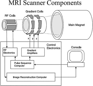
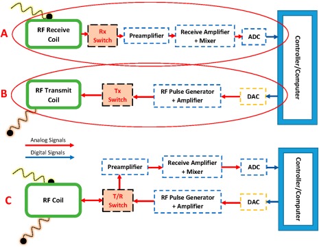
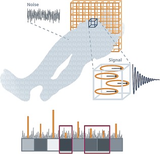
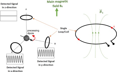
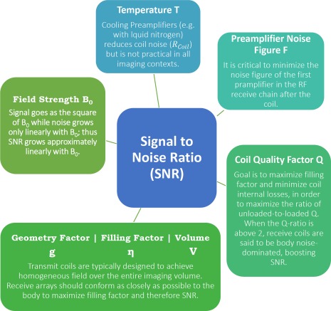
Radiofrequency (RF) coils are an essential MRI hardware component. They directly impact the spatial and temporal resolution, sensitivity, and uniformity in MRI. Advances in RF hardware have resulted in a variety of designs optimized for specific clinical applications. RF coils are the "antennas" of the MRI system and have two functions: first, to excite the magnetization by broadcasting the RF power (Tx-Coil) and second to receive the signal from the excited spins (Rx-Coil). Transmit RF Coils emit magnetic field pulses ( B1+) to rotate the net magnetization away from its alignment with the main magnetic field (B0 ), resulting in a transverse precessing magnetization. Due to the precession around the static main magnetic field, the magnetic flux in the receive RF Coil ( B1-) changes, which generates a current I. This signal is "picked-up" by an antenna and preamplified, usually mixed down to a lower frequency, digitized, and processed by a computer to finally reconstruct an image or a spectrum. Transmit and receive functionality can be combined in one RF Coil (Tx/Rx Coils). This review looks at the fundamental principles of an MRI RF coil from the perspective of clinicians and MR technicians and summarizes the current advances and developments in technology.
Level of evidence: 1 Technical Efficacy: Stage 6.
Keywords: RF coil; arrays; clinical application; coil array design; novel RF coils; signal-to-noise ratio.
© 2018 International Society for Magnetic Resonance in Medicine.
Figures
Similar articles
-
Radiofrequency-transparent local B0 shimming coils using float traps.Magn Reson Med. 2025 Apr;93(4):1833-1841. doi: 10.1002/mrm.30361. Epub 2024 Nov 4. Magn Reson Med. 2025. PMID: 39497505 Free PMC article.
-
Basic Principles of and Practical Guide to Clinical MRI Radiofrequency Coils.Radiographics. 2022 May-Jun;42(3):898-918. doi: 10.1148/rg.210110. Epub 2022 Apr 8. Radiographics. 2022. PMID: 35394887
-
Performance evaluation of RF coils integrated with an RF-penetrable PET insert for simultaneous PET/MRI.Magn Reson Med. 2019 Feb;81(2):1434-1446. doi: 10.1002/mrm.27444. Epub 2018 Sep 9. Magn Reson Med. 2019. PMID: 30260501 Free PMC article.
-
Machine Learning for the Design and the Simulation of Radiofrequency Magnetic Resonance Coils: Literature Review, Challenges, and Perspectives.Sensors (Basel). 2024 Mar 19;24(6):1954. doi: 10.3390/s24061954. Sensors (Basel). 2024. PMID: 38544216 Free PMC article. Review.
-
Advancements in MR hardware systems and magnetic field control: B0 shimming, RF coils, and gradient techniques for enhancing magnetic resonance imaging and spectroscopy.Psychoradiology. 2024 Aug 14;4:kkae013. doi: 10.1093/psyrad/kkae013. eCollection 2024. Psychoradiology. 2024. PMID: 39258223 Free PMC article. Review.
Cited by
-
Dual-Channel Stretchable, Self-Tuning, Liquid Metal Coils and Their Fabrication Techniques.Sensors (Basel). 2023 Sep 1;23(17):7588. doi: 10.3390/s23177588. Sensors (Basel). 2023. PMID: 37688046 Free PMC article.
-
Implantable, Bioresorbable Radio Frequency Resonant Circuits for Magnetic Resonance Imaging.Adv Sci (Weinh). 2024 Jul;11(27):e2301232. doi: 10.1002/advs.202301232. Epub 2023 Jun 25. Adv Sci (Weinh). 2024. PMID: 37357139 Free PMC article.
-
Novel magnetic resonance imaging methodology for dynamic visualization of respiratory thoracic motion: a pilot feasibility study.Front Rehabil Sci. 2025 Aug 12;6:1540183. doi: 10.3389/fresc.2025.1540183. eCollection 2025. Front Rehabil Sci. 2025. PMID: 40874234 Free PMC article.
-
Design of standalone wireless impedance matching (SWIM) system for RF coils in MRI.Sci Rep. 2022 Dec 14;12(1):21604. doi: 10.1038/s41598-022-26143-9. Sci Rep. 2022. PMID: 36517622 Free PMC article.
-
Recent Advances in Radio-Frequency Coil Technologies: Flexible, Wireless, and Integrated Coil Arrays.J Magn Reson Imaging. 2022 Apr;55(4):1026-1042. doi: 10.1002/jmri.27865. Epub 2021 Jul 29. J Magn Reson Imaging. 2022. PMID: 34324753 Free PMC article. Review.
References
-
- Lauterbur PC. Image formation by induced local interactions: examples employing nuclear magnetic resonance. Nature 1973;242:190–191. - PubMed
-
- Mansfield P, and Grannell PK. NMR ‘diffraction’ in solids. J Phys C 1973;6:L422–L426.
-
- Klomp DWJ, van der Graaf M, Willemsen MAAP, van der Meulen APM, Heerschap A. Transmit/receive headcoil for optimal 1H MR spectroscopy of the brain in paediatric patients at 3T. MAGMA 2004;17:1–4. - PubMed
-
- Street AM. RF switch design. IEEE Training Course 2000: How to design RF circuits 2000;27:1–7.
-
- Tokumitsu T, Toyoda I, Aikawa M. Low voltage, high power T/R switch MMIC using LC resonators. In IEEE Microwave and Millimeter‐Wave Monolithic Circuits Symposium, Atlanta, GA, 1993.
Publication types
LinkOut - more resources
Full Text Sources
Other Literature Sources
Research Materials
