Review
. 2018 Mar-Apr;23(2):87-109.
doi: 10.1590/2177-6709.23.2.087-109.sar.

Twenty-year clinical experience with fixed functional appliances

Affiliations
Review

Twenty-year clinical experience with fixed functional appliances

Alexandre Moro et al. Dental Press J Orthod. 2018 Mar-Apr.

Abstract

Introduction: Considering the large number of fixed functional appliances, choosing the best device for your patient is not an easy task.

Objective: To describe the development of fixed functional appliances as well as our 20-year experience working with them.

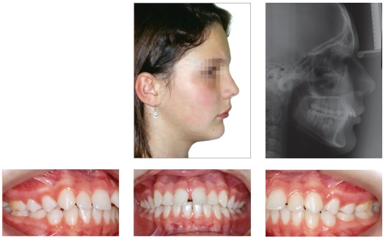
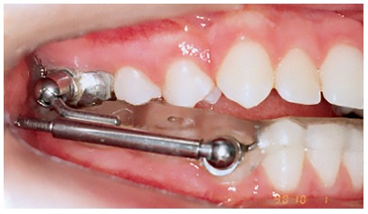
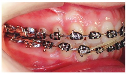
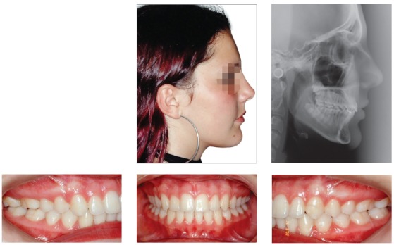
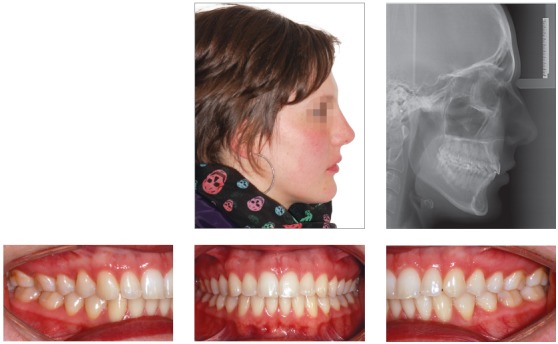
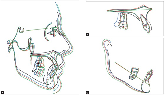
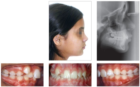
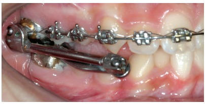
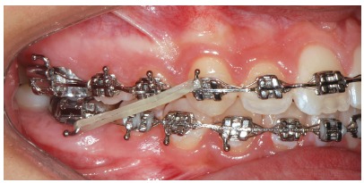
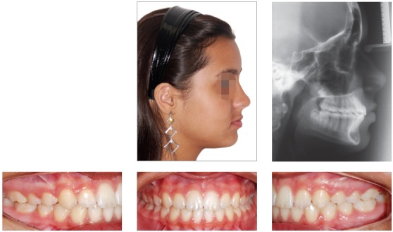
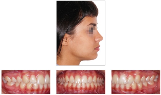
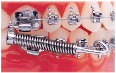
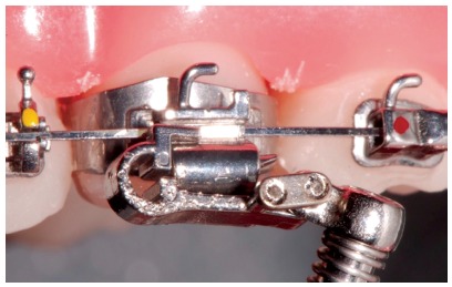
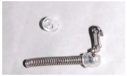
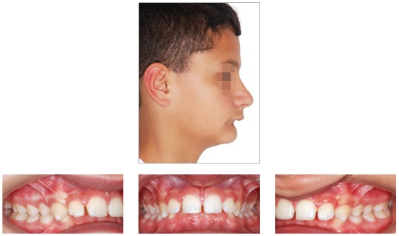
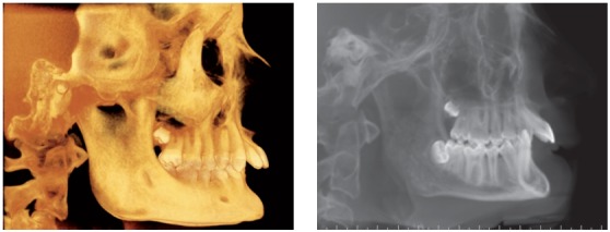
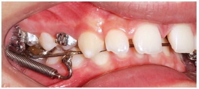
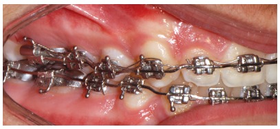
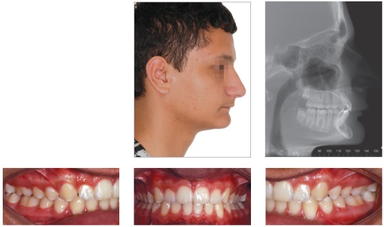
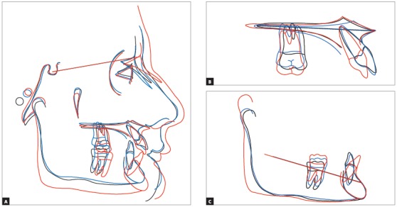
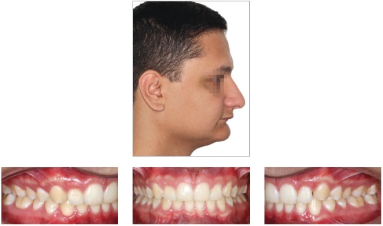
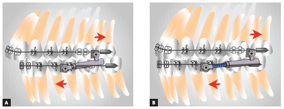
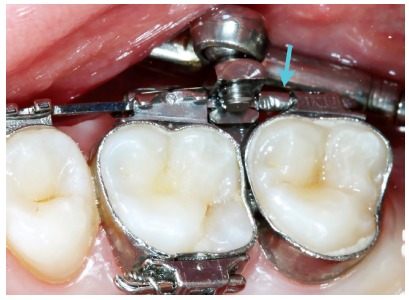
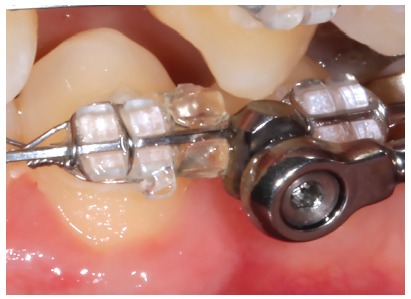
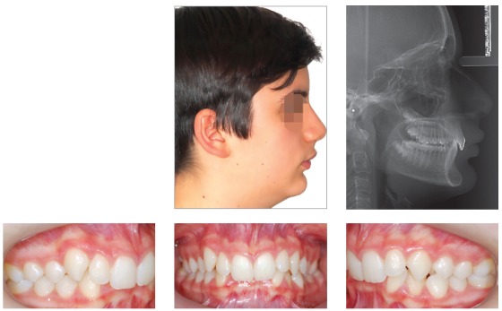
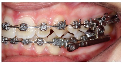
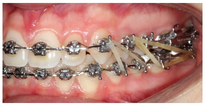
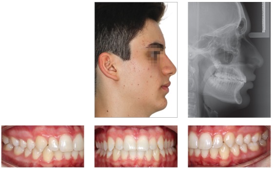
Methods: Fixed functional appliances are grouped into flexible, rigid and hybrid. They are different appliances, whose action is described here. Four clinical cases will be reported with a view to illustrating the different appliances.

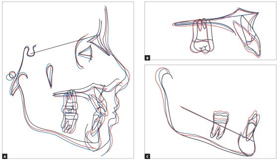
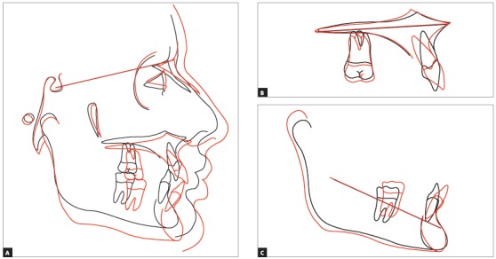
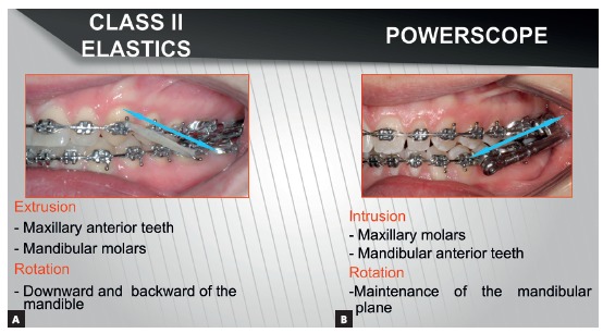
Conclusions: Rigid fixed functional appliances provide better skeletal results than flexible and hybrid ones. Flexible and hybrid appliances have similar effects to those produced by Class II elastics. They ultimately correct Class II with dentoalveolar changes. From a biomechanical standpoint, fixed functional appliances are more recommended to treat Class II in dolichofacial patients, in comparison to Class II elastics.

Introdução:: considerando-se o grande número de aparelhos propulsores mandibulares, não é uma tarefa fácil escolher o melhor deles para o seu paciente.

Objetivo:: descrever o desenvolvimento desses aparelhos e a experiência clínica de vinte anos dos autores na sua utilização.

Métodos:: os aparelhos funcionais fixos aqui apresentados foram classificados em flexíveis, rígidos e híbridos, e o modo de ação de cada um deles foi descrito e ilustrado por meio de quatro casos clínicos.

Conclusões:: os aparelhos propulsores rígidos fornecem mais resultados esqueléticos do que os flexíveis e os híbridos. Esses últimos têm efeito semelhante ao uso de elásticos com direção de Classe II e, basicamente, corrigem a má oclusão de Classe II com alterações dentoalveolares. Do ponto de vista biomecânico, os propulsores fixos estão mais indicados para tratar a Classe II em pacientes dolicofaciais do que os elásticos de Classe II.


Figures

Figure 1
Figure 1. Miniscope telescopic system: A) Rollo band; B) Universal nut; C) Barrel nut; D) Miniscope (right side); E) Applecore screw.
Figure 2
Figure 2. An illustration of true stimulation and temporary stimulation of mandibular growth. True stimulation indicates that growth occurs at a faster-than-expected rate during functional appliance therapy, then continues at the expected rate thereafter, so that the ultimate size of the mandible is larger. Temporary acceleration means that faster growth occurs during functional therapy, but slower growth thereafter ultimately brings the mandible back to the size that would be expected without treatment (Adapted from:Lai and McNamara23, 1998).
Figure 3
Figure 3. Tridimensional assessment carried out by means of colored maps after one year of treatment with the Herbst appliance: A) frontal view; B) lateral view; C) lateral view of mesh superimposition; D) mandibular occlusal view.
Figure 4
Figure 4. TMJ laminagraphic images of patient treated with Cantilever Bite Jumper (CBJ). A) Before treatment onset, condyles were centered in the fossa. At appliance placement, the mandible was moved 9mm (07/08) forward. Two and four months later, double condyle and mandibular fossa images are seen as a result of bone remodeling. B) Seven months later (11/03), the condyle was back to its primary position.
Figure 5
Figure 5. Pretreatment records: Extra and intraoral photographs, and lateral cephalogram.
Figure 6
Figure 6. Intraoral right photograph showing Herbst appliance placement.
Figure 7
Figure 7. Intraoral right photograph showing fixed appliance.
Figure 8
Figure 8. Posttreatment records: Extra and intraoral photographs, and lateral cephalogram.
Figure 9
Figure 9. Posttreatment records at ten years: Extra and intraoral photographs, and lateral cephalogram.
Figure 10
Figure 10. A) Cephalometric tracings superimposition on the cranial base (black = initial; blue = after Herbst appliance; red = treatment completion; green = ten years after treatment completion). B) Maxillary superimposition (ANS-PNS registered at ANS). C) Mandibular superimposition (Xi-Pm registered at Pm).
Figure 11
Figure 11. Pretreatment records: Extra and intraoral photographs, and lateral cephalogram.
Figure 12
Figure 12. Intraoral right photograph after Herbst appliance placement.
Figure 13
Figure 13. Intraoral right photograph showing fixed appliance.
Figure 14
Figure 14. Posttreatment records: Extra and intraoral photographs, and lateral cephalogram.
Figure 15
Figure 15. A) Cephalometric tracings superimposition on the cranial base (black = initial; blue = after Herbst appliance; red = treatment completion). B) Maxillary superimposition (ANS-PNS registered at ANS). C) Mandibular superimposition (Xi-Pm registered at Pm).
Figure 16
Figure 16. Posttreatment records at 5.5 years: Extra and intraoral photographs.
Figure 17
Figure 17. Forsus Fatigue Resistant Device with L-pin Module, released in 2002.
Figure 18
Figure 18. Forsus Fatigue Resistant Device with EZ2 Module. Note two screws on maxillary molar clip (modification released in 2009).
Figure 19
Figure 19. Forsus appliance push rods in different sizes: extra short push rod = 22 mm; short push rod = 25 mm; median push rod: 29 mm; large push rod = 32 mm; extralarge push rod = 35 mm.
Figure 20
Figure 20. Measurement gauge placement. The tool is used to choose the size of Forsus appliance. With the patient biting and having the mandible in maximal intercuspation, the clinician places the buccal portion of the measurement gauge behind the maxillary molar tube. The tool is then tipped and the number near the distal portion of the canine bracket or mandibular first premolar is chosen.
Figure 21
Figure 21. Plastic caps used to protect patient’s cheek when Forsus appliance is used.
Figure 22
Figure 22. Pretreatment records: Extra and intraoral photographs.
Figure 23
Figure 23. Initial tomographic scan in lateral view and lateral cephalogram.
Figure 24
Figure 24. Intraoral photograph showing X-bow placement.
Figure 25
Figure 25. Intraoral photograph showing fixed appliance.
Figure 26
Figure 26. Posttreatment records: Extra and intraoral photographs, and lateral cephalogram.
Figure 27
Figure 27. A) Cephalometric tracings superimposition on the cranial base (black = initial; blue = after X-bow appliance; red = treatment completion). B) Maxillary superimposition (ANS-PNS registered at ANS). C) Mandibular superimposition (Xi-Pm registered at Pm).
Figure 28
Figure 28. Posttreatment records at 5 years: Extra and intraoral photographs.
Figure 29
Figure 29. PowerScope appliance spring. The photograph shows how the spring remains inside the appliance.
Figure 30
Figure 30. Components of PowerScope.
Figure 31
Figure 31. Evaluation of PowerScope activation: A) Appliance placed without activation, as evinced by three black lines; B) Mid tube being pushed backwards with a tool; C) 6-mm spacer placement for total spring activation. Note that the black lines disappear, while a 1.5-mm depression in intermediate tube appears (marked in green).
Figure 32
Figure 32. Activation indicator. Should three marks appear, this means the spring is not activated. Should two marks appear, this means the spring is partially activated. Should no marks appear, the appliance is totally activated.
Figure 33
Figure 33. Use of spacers in mandibular push rod: A) No spacer; B) After placement of six 1-mm spacers.
Figure 34
Figure 34. Step-by step placement: A) Initially, screw end should be leveled with the internal stop surface; B) Subsequently, the attachment nut is tipped in 45° relative to the arch; C) The nut should be pressed gently with clinician’s index finger, so as to fit the attachment nut into the arch and allow the appliance to remain parallel the occlusal plane. Thereafter, key should be turned with clinician’s right hand in short turns. Placement should be performed first in the maxilla and then in the mandible.
Figure 35
Figure 35. Appliance placement outside the mouth. Note the arch inside the attachment nut.
Figure 36
Figure 36. Mirror used to check whether the screw is completely closing the nut slot, thus preventing the attachment nut from falling loose.
Figure 37
Figure 37. Stop placement on the mesial surface of maxillary second molar tube.
Figure 38
Figure 38. Elastomeric ligature (With Guard, 3M Unitek, Monrovia, CA, USA) placement on distal wing of mandibular first premolar bracket. A rotation edge can also be used.
Figure 39
Figure 39. Pretreatment records: Extra and intraoral photographs, and lateral cephalogram.
Figure 40
Figure 40. Intraoral left photograph showing PowerScope appliance placement.
Figure 41
Figure 41. Intraoral left photograph showing fixed appliance at treatment completion.
Figure 42
Figure 42. Posttreatment records: Extra and intraoral photographs, and lateral cephalogram.
Figure 43
Figure 43. A) Cephalometric tracings superimposition on the cranial base (black = initial; red = treatment completion). B) Maxillary superimposition (ANS-PNS registered at ANS). C) Mandibular superimposition (Xi-Pm registered at Pm).
Figure 44
Figure 44. Direction of force for Class II correction: A) Class II elastics with traction force; B) Fixed functional appliance with impulsion force.
Figure 45
Figure 45. Class II compensatory treatment with PowerScope 2 in adult patient not willing to undergo orthognathic surgery.

References

    1. Hanks SD. Trying to get out of the 20th century: a partial translation of Emil Herbst's 1910 text. World J Orthod. 2000;1(1):9–16.
    1. Pancherz H. Treatment of Class II malocclusion by jumping the bite with the Herbst appliance a cephalometric investigation. Am J Orthod. 1979;76(4):423–442. - PubMed
    1. Ritto AK, Ferreira AP. Fixed functional appliances--a classification. Funct Orthod. 2000;17(2):12–30. - PubMed
    1. Foncatti CF, Castanha Henriques JF, Janson G, Caldas W, Garib DG. Long-term stability of Class II treatment with the Jasper jumper appliance. Am J Orthod Dentofacial Orthop. 2017;152(5):663–671. - PubMed
    1. Coelho CM., Filho Mandibular protraction appliances for Class II treatment. J Clin Orthod. 1995;29(5):319–336. - PubMed

MeSH terms