. 2018 Jun 13;9(1):2309.
doi: 10.1038/s41467-018-04782-9.

The role of water in fault lubrication

Affiliations

The role of water in fault lubrication

Yijue Diao et al. Nat Commun. .

Abstract

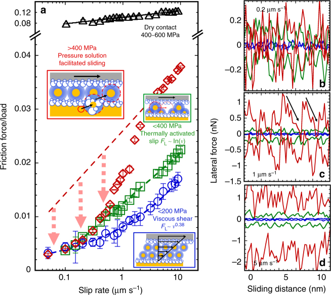
The friction between two adjacent tectonic plates under shear loading may dictate seismic activities. To advance the understanding of mechanisms underlying fault strength, we investigate the frictional characteristics of calcite in an aqueous environment. By conducting single-asperity friction experiments using an atomic force microscope, here we show three pathways of energy dissipation with increasing contact stresses: viscous shear of a lubricious solution film at low normal stresses; shear-promoted thermally activated slip, similar to dry friction but influenced by the hydrated ions localized at the interface; and pressure-solution facilitated slip at sufficiently high stresses and slow sliding velocities, which leads to a prominent decrease in friction. It is also shown that the composition of the aqueous solution affects the frictional response. We use this nanoscale evidence to scrutinize the role of brines on fault behavior and argue that pressure solution provides a weakening mechanism of the fault strength at the level of single-asperity contacts.


Conflict of interest statement

The authors declare no competing interests.

Figures

Fig. 1
Fig. 1
Friction between calcite and an AFM tip as a function of velocity in CaCl2 solutions equilibrated with calcite. CaCl2 concentrations are selected as a, f, k 0 mM, b, g, l 1 mM, c, h, m 10 mM, d, i, n 100 mM, and e, j, o 1 M. The friction force in ae LS regime (0.5–2 nN, σn ≤200 MPa) and ko HS regime (20–50 nN, σn > 400 MPa) is plotted as a function of speed in log–log scale, while it is plotted in linear-log scale in fj IS regime (5-20 nN, σn~200–400 MPa). Friction increases with velocity under all conditions. The calculated contact stresses at each load are summarized in Supplementary Table 1. The solid lines show the fits of ae Eq. (1) and fj Eq. (2) to the experimental data. The exponent n is shown for each load in ae. Error bars give the variation in friction across ten friction loops; the variation is often so small that the error bars are smaller than the symbol size, and thus, difficult to see. The blue shades are for LS regime, green for IS regime, and red for HS regime, while the intensity (from light to dark) indicates an increase of load (for each regime). Inset of e and j shows a scanning electron microscopy image of the tip used in LS and IS regimes (with a radius of ~150 nm), and the inset of o shows the tip (with a radius of 100 nm) used in the HS regime. Inset of n shows the velocity-dependent friction force in linear-log scale at two selected loads, 10 and 50 nN, and the shadow qualitatively indicates the reduction of the frictional strength mediated by pressure solution. The arrows in ko point at the crossover of the velocity-dependent friction force and is the qualitative footprint for pressure solution of calcite
Fig. 2
Fig. 2
Stress-activation length and crossover velocity. a Schematics of the shear-promoted thermally activated slip in the IS regime (σn ~ 200–400 MPa). b Stress-activation length λ obtained from fitting Eq.(2) to the velocity-dependent friction force in the IS regime. The error bars show the root-mean-square error of the fits. The region under the gray dashed line shows the range of λ in dry experiments, which is described here by the shear-promoted thermally activated slip of the surface atoms for comparison purposes. Tip radius = 150 nm. c Crossover velocities vc in the HS regime (σn > 400 MPa); tip radius = 100 nm. The results in b, c are shown for the selected CaCl2 concentrations displayed in the legends
Fig. 3
Fig. 3
Friction between calcite and an AFM tip as a function of load in CaCl2 solutions. The selected concentrations are shown in the legend in b. The results are shown at sliding speeds of a 0.2 µm s–1 and b 2 µm s–1, in green for the IS regime and in red for the HS regime. Error bars show the variation in friction over ten friction loops. Tip radius = 100 nm. The insets show the friction coefficient (µ)—calculated as the slope of the friction force vs. normal load—in the LS, IS, and HS regimes at the two selected sliding velocities; the friction coefficient under dry conditions is shown as reference (dashed gray line). The box diagrams illustrate the variation of µ with CaCl2 concentration; the error bars give the standard deviation of µ. The friction coefficient in the LS regime was calculated with experimental data measured with an AFM tip with a smaller stiffness (not shown here). The friction coefficient in the HS regime was calculated above the load Lc and does not include the plateau at the highest loads for simplification. The dependence of friction on velocity shown in Fig. 1 is reflected in the increase of the friction coefficient with velocity (0.2 and 2 µm s–1); note the different scale on the Y-axis
Fig. 4
Fig. 4
Friction between calcite and an AFM tip in a dry nitrogen atmosphere. Friction force as a function of a velocity and b applied load. Tip radius = 100 nm. Under dry conditions, the friction force—higher than in wet experiments—still scales with the logarithm of the sliding velocity at contact stresses as high as 620 MPa. For comparison purposes, friction is described as a shear-promoted thermally activated slip that accounts for the rupture of the adhesive bonds between the surface atoms on calcite and tip. Stress-activation lengths λ obtained by fitting Eq. (2) to the velocity-dependent friction force are shown in a for each load
Fig. 5
Fig. 5
Velocity-dependent frictional strength in LS, IS and HS regimes and corresponding lateral forces as a function of the sliding distance. a Rate-strengthening frictional strength (shown as the friction force divided by the applied load) of a single-asperity contact between calcite and an AFM tip in a 100 mM CaCl2 solution at low ( ≤ 200 MPa, blue circles, LS), intermediate (200–400 MPa, green squares, IS) and high normal stresses ( > 400 MPa, red diamonds, HS), with the schematics showing the three identified friction mechanisms. The black symbols represent the frictional strength of the dry single-asperity contact (Fig. 4) for comparison. At low contact stresses (LS regime), the brine lubricates the single-asperity contact causing a significant decrease in friction when compared to the dry contact (black). By further increasing the stress (200–400 MPa, IS regime); the response to shear in this regime is described as a shear-promoted thermally activated slip of the localized hydrated ions on the surface, which leads to a logarithmic dependence of friction on velocity over the investigated range ( ≤ 10 µm s–1). At high contact stresses ( > 400 MPa, HS regime), the pronounced weakening of the single-asperity contact results from pressure-induced dissolution of calcite, if the contact time is sufficiently large. The red dashed line gives the calculated friction force according to Eq. (2), as in the IS regime, and extrapolated to lower velocities; the arrows illustrate the decrease in the frictional strength provided by pressure solution. bd Representative lateral force as a function of the sliding distance in the three regimes at selected slip rates. The color scheme is the same as in a, i.e., blue for LS regime, green for IS regime, and red for HS regime. Note the different scale on the Y-axis

Similar articles

Cited by

References

    1. Brace WF, Byerlee JD. Stick–slip as a mechanism for earthquakes. Science. 1966;153:990–992. doi: 10.1126/science.153.3739.990. - DOI - PubMed
    1. Scholz, C. H. The Mechanics of Earthquakes and Faulting, 2nd edn. (Cambridge University Press, Cambridge, 2002).
    1. Ruina A. Slip instability and state variable friction laws. J. Geophys. Res. 1983;88:359–370. doi: 10.1029/JB088iB12p10359. - DOI
    1. Audet P, Schwartz SY. Hydrologic control of forearc strength and seismicity in the Costa Rican subduction zone. Nat. Geosci. 2013;6:852–855. doi: 10.1038/ngeo1927. - DOI
    1. Marone C. Laboratory-derived friction laws and their application to seismic faulting. Annu. Rev. Earth. Planet. Sci. 1998;26:643–696. doi: 10.1146/annurev.earth.26.1.643. - DOI

Publication types

LinkOut - more resources