. 2018 Jun 7:12:31.
doi: 10.3389/fnbot.2018.00031. eCollection 2018.

Switching in Feedforward Control of Grip Force During Tool-Mediated Interaction With Elastic Force Fields

Affiliations

Switching in Feedforward Control of Grip Force During Tool-Mediated Interaction With Elastic Force Fields

Olivier White et al. Front Neurorobot. .

Abstract

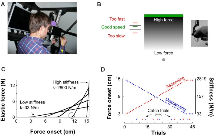
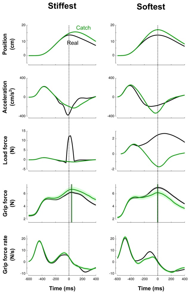
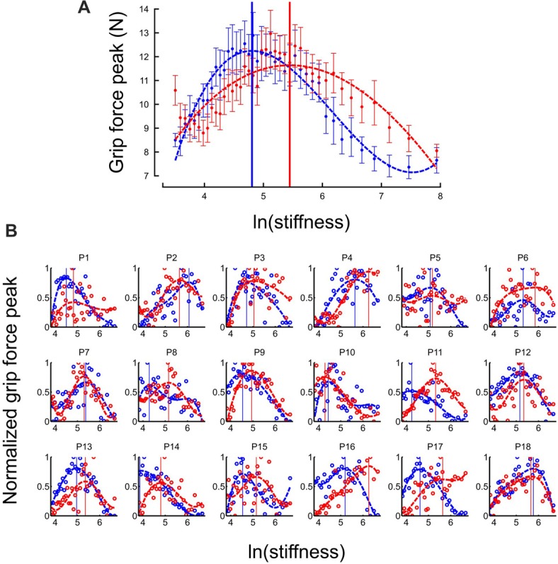
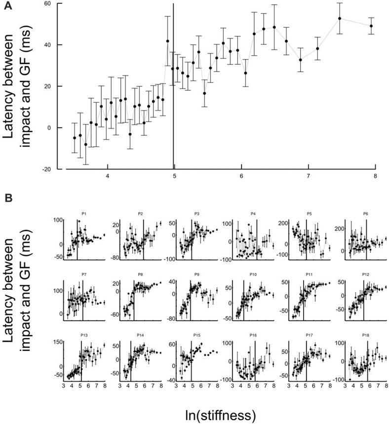
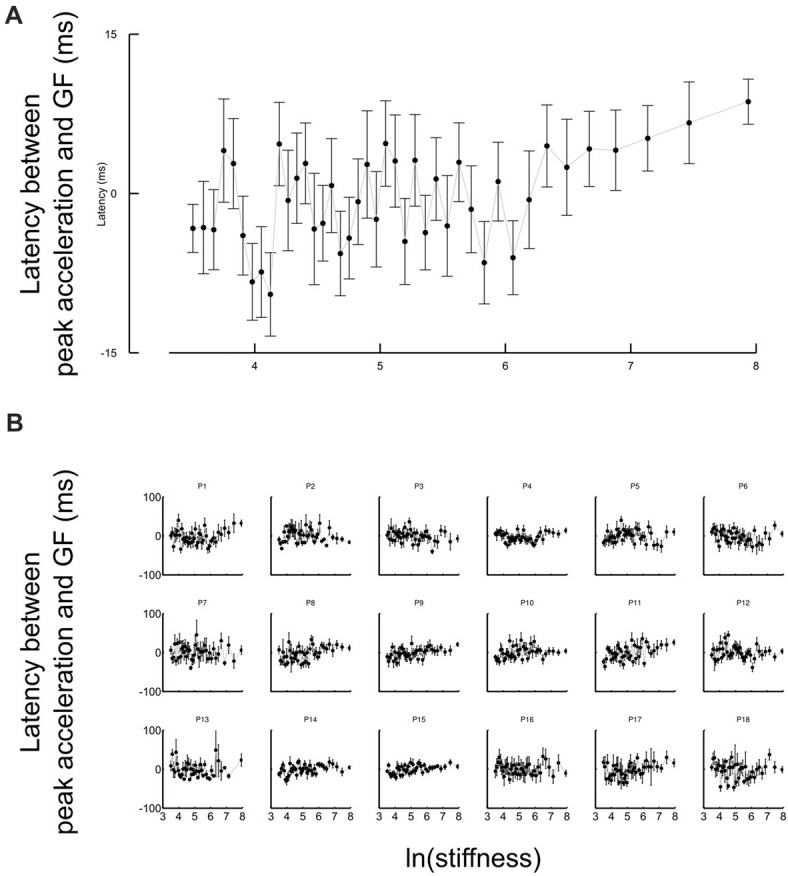
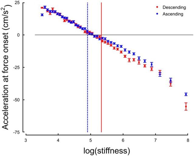
Switched systems are common in artificial control systems. Here, we suggest that the brain adopts a switched feedforward control of grip forces during manipulation of objects. We measured how participants modulated grip force when interacting with soft and rigid virtual objects when stiffness varied continuously between trials. We identified a sudden phase transition between two forms of feedforward control that differed in the timing of the synchronization between the anticipated load force and the applied grip force. The switch occurred several trials after a threshold stiffness level in the range 100-200 N/m. These results suggest that in the control of grip force, the brain acts as a switching control system. This opens new research questions as to the nature of the discrete state variables that drive the switching.

Keywords: grip force; internal model; phase transition; stiffness; uncertainty.


Figures

Figure 1
Figure 1
Description of experimental setup and procedures. (A) View of the virtual reality stereoscopic display. A participant is seated and holds the transducer with his right hand. The vertical yellow arrow that points downward represents the pushing force operated by the robotic device. (B) A gray sphere was moved toward a green target through a parameterized elastic force field. The gray gradient represents the magnitude of the force field for a given stiffness. It is low far from the target (bright gray) and increases when vertical position approaches the target (dark gray). Left: feedback of achieved peak velocity. The right inset depicts the force sensor attached to the end of the robot handle held in precision grip. (C) Examples of force-position trajectories of five elastic force fields parametrized by five pairs of stiffness levels and force onset position. Force onset occurred between 3 cm and 14.5 cm above home position. The steeper the slope the stiffer the force field. The circle highlights the second order interpolation between a null force field and a linear elastic force field. (D) Structure of “Ascending” and “Descending” blocks, where stiffness increases (red) and decreases (blue), respectively. Catch trials, for which the stiffness is set to 0 N/m, are positioned at the bottom of the trace.
Figure 2
Figure 2
Averaged traces corresponding to the stiffest (left column) trials and softest (right column) trials across blocks and participants. Top to bottom: vertical position, vertical acceleration, load force, grip force and grip force rate are depicted as a function of time. Black and green lines correspond to real and catch trials, respectively. All traces are aligned with peak of impact (vertical dashed cursor across panels, time 0). Cursors for the grip force traces are positioned at their respective maximum. The lags calculated between peaks of grip and elastic forces illustrate the difference between high-stiffness (lag = 40 ms, SD = 6 ms) and low-stiffness (lag = 4 ms, SD = 6 ms) conditions. Error shade areas correspond to SEM. Traces are not normalized.
Figure 3
Figure 3
Grip force is adapted to stiffness. (A) Distribution of grip force maximum (averaged across participants) in function of ln(stiffness) in “Ascending” (red trace) and “Descending” block conditions (blue trace). The dashed lines are the best fourth order polynomial fits of each series. Goodness of fit: r2 = 0.72 in “Ascending” condition and r2 = 0.84 in “Descending” condition. The vertical cursors are positioned at peak grip force (“Ascending”: 5.07; “Descending”: 4.89, which correspond to stiffness of 159.7 N/m and 133.2 N/m, respectively). Error bars are between participants SE. (B) Individual normalized plots showing the same behavior at the participant level (except for participant 14 in the “Descending” condition).
Figure 4
Figure 4
Grip force control switches for certain stiffness values. (A) Average lags across participants between grip force peak and impact as a function of the natural logarithm of stiffness. The same lags are plotted for individual participants in the lower panel (B). The lags vary with stiffness. Positive values of latencies mean that grip force peaks lag impacts. Black cursors are positioned at the ln(stiffness) identified from grip force peaks that correspond to the average between the “Ascending” and “Descending” conditions. Error bars are SEM.
Figure 5
Figure 5
Grip force is synchronized with the inertial, acceleration-dependent, force whatever the stiffness values. (A) Average lags across participants between the first local grip force peak and the acceleration shortly after movement onset as a function of the natural logarithm of stiffness. The same lags are plotted for individual participants in the lower panel (B). The lags are distributed around zero. Error bars are SEM.
Figure 6
Figure 6
Hand acceleration at force onset (or expected) in function of natural logarithm of stiffness for Ascending (blue) and Descending trials. The horizontal black line is positioned at sign(acc) = 0. The two vertical cursors are positioned at the thresholds identified on the distribution of grip force peaks.

Similar articles

Cited by

References

    1. Asai Y., Tasaka Y., Nomura K., Nomura T., Casadio M., Morasso P. (2009). A model of postural control in quiet standing: robust compensation of delay-induced instability using intermittent activation of feedback control. PLoS One 4:e6169. 10.1371/journal.pone.0006169 - DOI - PMC - PubMed
    1. Augurelle A.-S., Penta M., White O., Thonnard J.-L. (2003). The effects of a change in gravity on the dynamics of prehension. Exp. Brain Res. 148, 533–540. 10.1007/s00221-002-1322-3 - DOI - PubMed
    1. Barbiero M., Rousseau C., Papaxanthis C., White O. (2017). Coherent multimodal sensory information allows switching between gravitoinertial contexts. Front. Physiol. 8:290. 10.3389/fphys.2017.00290 - DOI - PMC - PubMed
    1. Ben-Itzhak S., Karniel A. (2008). Minimum acceleration criterion with constraints implies bang-bang control as an underlying principle for optimal trajectories of arm reaching movements. Neural Comput. 20, 779–812. 10.1162/neco.2007.12-05-077 - DOI - PubMed
    1. Binsted G., Elliott D. (1999). Ocular perturbations and retinal/extraretinal information: the coordination of saccadic and manual movements. Exp. Brain Res. 127, 193–206. 10.1007/s002210050789 - DOI - PubMed

LinkOut - more resources