Review
. 2018 Aug 28;47(17):6486-6504.
doi: 10.1039/c8cs00187a.

Silkworm silk-based materials and devices generated using bio-nanotechnology

Affiliations
Review

Silkworm silk-based materials and devices generated using bio-nanotechnology

Wenwen Huang et al. Chem Soc Rev. .

Abstract

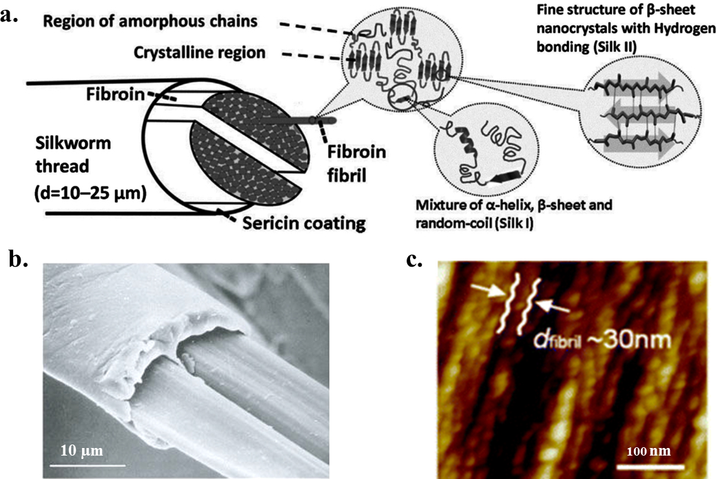
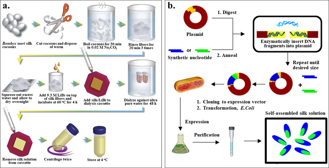
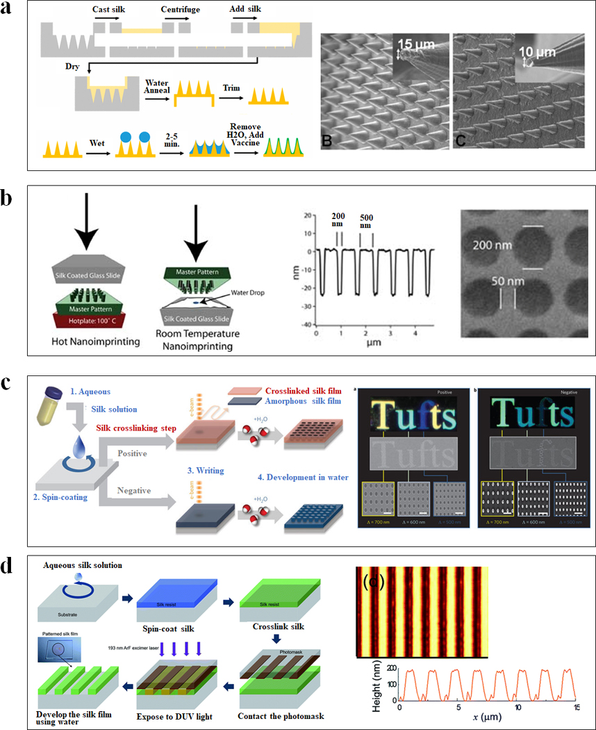
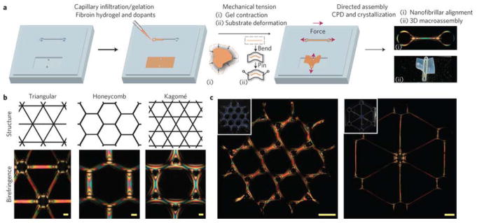
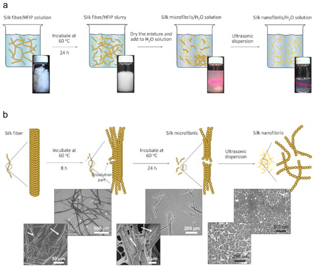
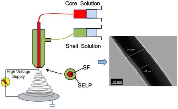
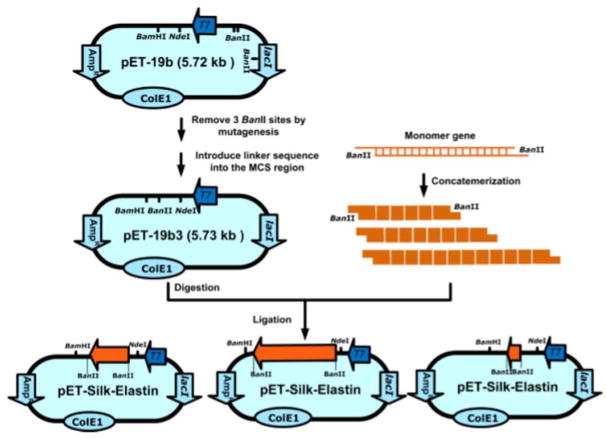
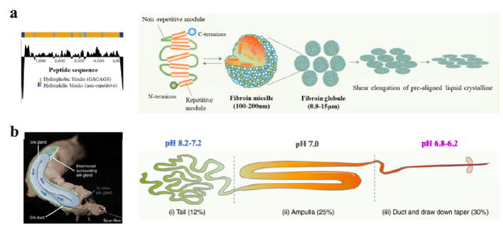
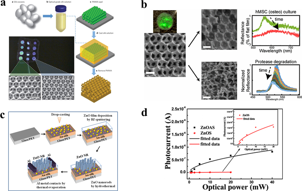
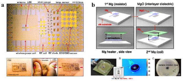
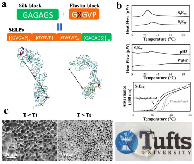
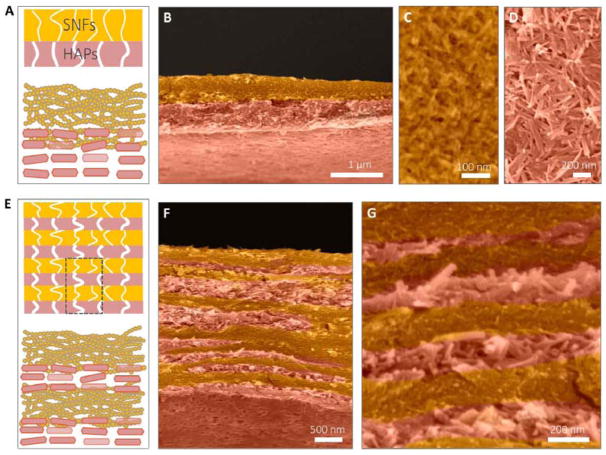
Silks are natural fibrous protein polymers that are spun by silkworms and spiders. Among silk variants, there has been increasing interest devoted to the silkworm silk of B. mori, due to its availability in large quantities along with its unique material properties. Silk fibroin can be extracted from the cocoons of the B. mori silkworm and combined synergistically with other biomaterials to form biopolymer composites. With the development of recombinant DNA technology, silks can also be rationally designed and synthesized via genetic control. Silk proteins can be processed in aqueous environments into various material formats including films, sponges, electrospun mats and hydrogels. The versatility and sustainability of silk-based materials provides an impressive toolbox for tailoring materials to meet specific applications via eco-friendly approaches. Historically, silkworm silk has been used by the textile industry for thousands of years due to its excellent physical properties, such as lightweight, high mechanical strength, flexibility, and luster. Recently, due to these properties, along with its biocompatibility, biodegradability and non-immunogenicity, silkworm silk has become a candidate for biomedical utility. Further, the FDA has approved silk medical devices for sutures and as a support structure during reconstructive surgery. With increasing needs for implantable and degradable devices, silkworm silk has attracted interest for electronics, photonics for implantable yet degradable medical devices, along with a broader range of utility in different device applications. This Tutorial review summarizes and highlights recent advances in the use of silk-based materials in bio-nanotechnology, with a focus on the fabrication and functionalization methods for in vitro and in vivo applications in the field of tissue engineering, degradable devices and controlled release systems.


Figures

Figure 1
Figure 1. Hierarchical structure of B. mori silk
(a) B. mori silk fiber has a core-shell type structure, with silk fibroin as the inner core and sericin as the outer coating. Each silk fibroin brin is composed of numerous interlocking fibroin fibrils. Inside the fibroin fibrils, the β-sheet nanocrystals are connected by amorphous chains to form a heteronanocomposite. β-sheet nanocrystals are composed of stacked β-sheets with peptide chains connected by hydrogen bonds in each sheet. The lattice constants of the orthogonal unit cell of β-sheet nanocrystal are a = 0.938 nm, b = 0.949 nm, and c = 0.698 nm for silkworm, B. mori, silk. (b) Scanning electron microscopy image of native B. mori silkworm silk (scale bar: 10 μm). (c) Atomic force microscopy image of the fibroin fibril structure in B. mori silkworm silk with a sequence of linked segments (scale bar: 100 nm). Adapted with permission from refs , and . Copyright 2002 Springer Nature, 2013 Royal Society of Chemistry, and 2017 MDPI AG, Basel, Switzerland.
Figure 2
Figure 2. Production of silk protein solutions
Generating silk protein solutions is essential for their applications as functional materials. Among various silk protein synthesis methods, two methods are industrially scalable: silk fibroin extraction and bioengineered silk fermentation. (a) Schematic of the silk fibroin extraction procedure for the production of B. mori regenerated silk fibroin (RSF). (b) General biosynthesis scheme of bioengineered silks using recombinant DNA technology. Adapted with permission from refs and . Copyright 2011 Springer Nature, and 2015 Springer Nature.
Figure 3
Figure 3. Lithography of silk-based biomaterials
(a) Schematic of soft lithography for vaccine-coated silk fibroin microneedles. SEM images of cone shaped microneedles prepared from an aqueous silk solution with different shapes and geometries. (b) Schematic diagrams of two nanoimprinting processes: hot embossing and room-temperature embossing. SEM image of a silk film imprinted with a periodic array of 200 nm diameter 30 nm height chromium nanoparticles separated by 250 nm. (c) Schematic of all-water-based electron-beam patterning on a silk film. Dark-field and electron microscopy images of silk nanostructures generated on positive and negative resist. (d) Schematic diagrams showing the ArF excimer laser photolithography process to form high-resolution silk fibroin micropatterns. Atomic force microscopy image of the patterned silk suggested the feature was around 190 nm in height and 1 μm in line width. Adapted with permission from refs , , , and . Copyright 2010 WILEY-VCH, 2013 WILEY-VCH, 2014 Springer Nature, 2016 The Royal Society of Chemistry and 2017 American Chemical Society.
Figure 4
Figure 4. Mechanical tension-mediated formation of patterned nanofibrillar structure
(a) General schematic of the directed assembly protocol. Aqueous silk fibroin is mixed with crosslinkers hydrogen peroxide and horseradish peroxidase and infiltrated/gelled in a PDMS mold. Mechanical tension is subsequently introduced by either contraction of the gel in mixtures of ethanol and water, or direct deformation of the elastomeric substrate. Finally, as the structures undergo critical point drying (CPD), β-sheet physical crosslinking in the silk is induced, stabilizing the material in its mechanically modified state. The final structure possesses tension-engineered nano-, micro- and macrostructure. b, Birefringence of sample microscale, nanofibrillar unit cells generated from periodic shapes. Scale bars, 100 μm. (c) Large-scale structures composed of tri-hexagonal and triangular components. Inset: camera images of the whole structure taken under diffuse white light. Scale bars, 1 mm. Adapted with permission from ref . Copyright 2017 Springer Nature.
Figure 5
Figure 5. Liquid exfoliation process of silk fiber
(a) Schematic and photographs showing the fabrication steps and their relevant solution. Step 1: silk fiber immersed in hexafluoroisopropanol (HFIP) solution with a weight ratio of 1:30 and the mixture was incubated for 24 h to obtain silk fiber/silk microfibers (SMFs) slurries. Step 2: the dried silk fiber slurries were transferred to H2O solution and the silk fiber precipitation was removed to gain SMFs dispersion. Step 3: the SNFs dispersion was prepared via ultrasonic treatment. (b) Schematic (top row) of liquid exfoliation of silk fiber and representative optical microscopy (the first two images in middle row) and scanning electron microscopy (SEM; the third image in middle row, and the images in bottom row) images of resultant products in each process. Silk fiber was dissolved by HFIP from the defect and ends and can be split to SMFs after 24 h. The white arrows in the optical microscopy and SEM images show the dissolution of silk fibers and SMFs. The SNFs with a diameter of 20 ± 5 nm are obtained after ultrasonic dispersion (SEM images in the last column). Adapted with permission from ref . Copyright 2016 WILEY-VCH.
Figure 6
Figure 6. All-aqueous coaxial electrospinning process
In this process, silk fibroin (SF) and silk-elastin-like protein polymer (SELP), both in aqueous solution and with high and low viscosity, respectively, were used as the inner (core) and outer (shell) layers of the nanofibers. The electrospun SF core solution served as a spinning aid for the nonelectrospinnable SELP shell solution. Uniform nanofibers with average diameters from 301 ± 108 nm to 408 ± 150 nm were obtained by adjusting processing parameters. Adapted with permission from ref . Copyright 2016 MDPI AG, Basel, Switzerland.
Figure 7
Figure 7. Construction of expression plasmids for recombinant silk elastin-like protein polymers
Multimerization of the silk monomer through “concatemerization” relying on the BanII restriction enzyme site. Adapted with permission from ref . Copyright 2011 American Chemical Society.
Figure 8
Figure 8. Self-assembly of silk fibroin micelles during spinning process
(a) Hydrophobicity pattern in B. mori silk fibroin heavy chain primary sequence and schematic model of the natural silk fiber assembly mechanism during the spinning processes. (b) Anatomical overview and illustration of the B. mori silk gland. The silkworm spinning gland is divided into three regions. The silk proteins are synthesized in the tail and transferred to the ampulla with increased concentration. In this region, the silk proteins are assembled to micelle-like structures with anisotropic liquid-crystalline properties. Finally, silk fiber formation occurs at decreased pH, shear stress and dehydration during pulling of the nematic silk proteins from the spigot (by the head motion of the worm). Adapted with permission from refs , and . Copyright 2003 Springer Nature and 2017 Springer Nature.
Figure 9
Figure 9. 3D printing of silk fibroin
(a) Design of printed structures (top) and CT-scan images of printed structures (bottom) showing hollow structure (vase) tissue scaffold and free-standing object (helix). Scale bars in A represent 1 mm. (b) Printed structure inside Nano-clay granular gel medium and image showing printing process (right). Adapted with permission from ref . Copyright 2018 Elsevier Ltd.
Figure 10
Figure 10. Enzyme catalyzed chemical crosslinking of silk fibroin
(a) Schematic representation of the crosslinking of tyrosine residues on silk molecules, these covalent bonds allow for chain extension creating highly elastic hydrogels. (b) Circular dichroism (CD) spectra of silk solution and enzymatically formed hydrogels, show a change to a helical structure and not β-sheet as found in other silk materials. Fluorescence excitation-emission spectra of (c) solution and (d) gel confirm the formation of dityrosine bonds. (e) The resultant hydrogels are optically clear and exhibit a blue fluorescence when irradiated with UV that is not present in the precursor solution. Adapted with permission from ref . Copyright 2014 WILEY-VCH.
Figure 11
Figure 11. Silk nanofibers for central nerves regeneration
The alignment of electrospun silk fibers depended on the speed of the rotating wheel collector: (a) fibers spun at static condition 0 m/s showing no alignment, and (b) fibers spun at 10 m/s showing optimal alignment. Scale bars: 5 μm. Retinal ganglion cells (RGC) culture on silk nanofibers: (c) phalloidin labelling of the actin filaments in RGC shows a neurite exhibiting a sharp change in direction of growth (arrow), while (d) merged image composed of the tetramethylrhodamine (TRITC) phalloidin (red), 4′,6-diamidino-2-phenylindole (DAPI) nuclear staining (blue) and autofluorescence (green) of the silk network demonstrates that the growth cone (the arrowheads in c and d) elongates in contact with silk fibers and that the sharp changes of direction correspond to silk crossroads (arrows in c and d). (e) SEM of RGC reveals that neurons grow in close contact with the silk. Adapted with permission from ref . Copyright 2011 WILEY-VCH.
Figure 12
Figure 12. Silk-based biomaterials for drug delivery
(a) Silk microneedles as applied to mouse skin: i) scanning electron micrograph of an individual silk microneedle, ii) silk microneedles patch, relative size comparison to mouse, iii) silk microneedles patch applied to animal skin, iv) skin after removal of microneedles patch, needle penetration marks are clearly visible, v) scanning electron micrograph of penetrated skin, and, vi) histology section of individual indentation site – epidermis was breached (arrow) allowing access to the underlying tissue; successful penetration of skin demonstrates sufficient mechanical strength of silk microneedles.(b) Silk microparticles: scanning electron microscopic images of silk particles prepared from 1/4 mass ratio silk/PVA blend films. (c) Silk nanoparticle: doxorubicin delivery into HeLa cells using SELP nanoparticles at: (A) 40 min and (B) 4 h incubation time. Adapted with permission from refs , and . Copyright 2010 Elsevier Ltd, 2011 WILEY-VCH, and 2014 American Chemical Society.
Figure 13
Figure 13. Silk inverse opals for smart cell culture
(a) Fabrication process for inverse opals. (b) Silk inverse opal degradation in response to a protease. Reflectance over time during the incubation of opals in protease XIV. (c) Fabrication process for lateral ZnO NRA photodetectors on Au-silk protein coated glass substrates. (d) Photocurrent as a function of incident optical power measured at 5 V for ZnOAS and ZnOS devices. Adapted with permission from refs , and . Copyright 2012 Springer Nature, 2017 IOP Publishing Ltd and 2017 American Chemical Society.
Figure 14
Figure 14. Silk-based flexible electronics
(a) Epidermal Electronics. Image of a demonstration platform for multifunctional electronics with physical properties matched to the epidermis. Mounting this device on a sacrificial, water-soluble film of PVA, placing the entire structure against the skin, with electronics facing down, and then dissolving the PVA leaves the device conformally attached to the skin through van der Waals forces, in a format that imposes negligible mass or mechanical loading effects on the skin. (b) Silk-based resorbable wireless heating devices for therapy and drug release. Schematic of the wireless heating device integrated with drug-loaded silk. The heating device comprises a resistor and a wireless coil encapsulated in silk fibroin. Drug molecules loaded in the silk film can be triggered to release under heat treatment for bacterial inhibition. Adapted with permission from refs and . Copyright 2011 American Association for the Advancement of Science and 2014 National Academy of Sciences USA.
Figure 15
Figure 15. Silk-elastin-like protein dynamic hydrogels
(a) SELP sequences and representative structures from simulation, at (i) 7 and (ii) 57°C. Dotted lines represent end-to-end molecular distance. (b) SELPs respond to temperature, a physical stimulus, exemplified by SELP with cysteine and phenylalanine mutation in the elastin domains, S2E8C and S2E8F; SELPs respond to pH, a chemical stimulus, exemplified by SELP with glutamic acid mutation in the elastin domains, S2E8E; and SELPs respond to phosphorylation, a biological stimulus, exemplified by with arginine mutation in elastin domains, S2E8R. (c) SEM images showing the micromorphology changes of S2E8R hydrogel samples in swollen states at 4°C (<LCST) and in contracted states at 37°C (>LCST) in deionized water. Adapted with permission from refs and . Copyright 2016 WILEY-VCH and 2017 American Chemical Society.
Figure 16
Figure 16. Silk-based multilayer filtration system
The double-layer structure of the SNF/HAP membranes was formed through vacuum filtration of 1 ml of SNF/HAP dispersion. (A) Schematic of double-layer structures. The top layer is the SNF-rich layer with small pore sizes. The bottom layer is the HAP layer with larger pore sizes. (B) Cross-sectional SEM image of a double-layer membrane. (C and D) Top-view SEM images of SNF-rich (C) and HAP-rich (D) layers. (E to G) The multilayer structure of the SNF/HAP membrane was generated from 3-ml SNF/HAP dispersion using a 3.5-cm-diameter mold. (E) Schematic of multilayer structures. (F) Cross section SEM image of a multilayer membrane. (G) High-resolution cross-sectional SEM image of a multilayer membrane. Adapted with permission from ref . Copyright 2017 American Association for the Advancement of Science.
Figure 17
Figure 17. Super-hydrophobic silk fabrics
(a) SEM images of nanostructures formed on a silk fabric exposed by ion beam treatment. The inset in shows micro-scale woven structures of the silk fabric. The scale bars are 1 μm and 400 μm. Static contact angle (black line) and shedding angle (blue line) of a water droplet measured after 30 s of hydrophobic coating with various ion beam durations. (b) The ion beam treated surface and (c) untreated surface of the same fabric maintaining super-hydrophobicity and hydrophilicity, respectively. Adapted with permission from ref . Copyright 2014 Royal Society of Chemistry.

References

    1. de la Rica R, Matsui H. Chemical Society Reviews. 2010;39:3499–3509. - PMC - PubMed
    1. Rockwood DN, Preda RC, Yucel T, Wang XQ, Lovett ML, Kaplan DL. Nature Protocols. 2011;6:1612–1631. - PMC - PubMed
    1. Guilbert S, Morel MH, Gontard N, Cuq B. Feedstocks for the Future: Renewables for the Production of Chemicals and Materials. 2006;921:334–350.
    1. Altman GH, Diaz F, Jakuba C, Calabro T, Horan RL, Chen JS, Lu H, Richmond J, Kaplan DL. Biomaterials. 2003;24:401–416. - PubMed
    1. Omenetto FG, Kaplan DL. Science. 2010;329:528–531. - PMC - PubMed

MeSH terms