. 2018 Jul 3;9(1):2576.
doi: 10.1038/s41467-018-05045-3.

Tunable and switchable magnetic dipole patterns in nanostructured superconductors

Affiliations

Tunable and switchable magnetic dipole patterns in nanostructured superconductors

Jun-Yi Ge et al. Nat Commun. .

Abstract

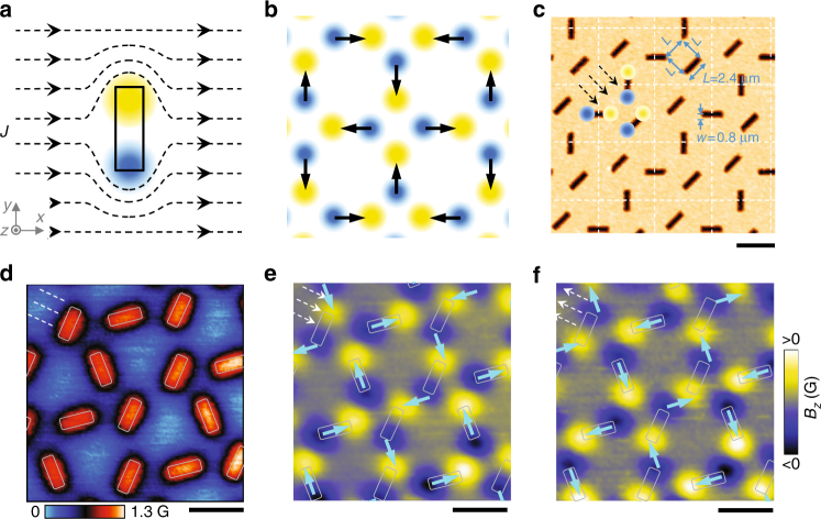
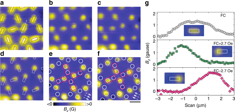
Design and manipulation of magnetic moment arrays have been at the focus of studying the interesting cooperative physical phenomena in various magnetic systems. However, long-range ordered magnetic moments are rather difficult to achieve due to the excited states arising from the relatively weak exchange interactions between the localized moments. Here, using a nanostructured superconductor, we investigate a perfectly ordered magnetic dipole pattern with the magnetic poles having the same distribution as the magnetic charges in an artificial spin ice. The magnetic states can simply be switched on/off by applying a current flowing through nanopatterned area. Moreover, by coupling magnetic dipoles with the pinned vortex lattice, we are able to erase the positive/negative poles, resulting in a magnetic dipole pattern of only one polarity, analogous to the recently predicted vortex ice. These switchable and tunable magnetic dipole patterns open pathways for the study of exotic ordering phenomena in magnetic systems.


Conflict of interest statement

The authors declare no competing interests.

Figures

Fig. 1
Fig. 1
Design and formation of the magnetic-charge-ice-like magnetic states. a Schematic view of a magnetic dipole generated by applying a current (indicated by dashed lines) around an elongated antidot. The yellow (blue) color indicates positive (negative) magnetic field. b Schematics of magnetic charge ice ground state ordering. The arrows, pointing from negative (blue) to positive (yellow) charges and mimicking spins, form the ground state of artificial square spin ice. c Atomic force microscopy image showing the topography of the sample. When applying a current in diagonal direction, the ground state magnetic-charge-ice-like pattern distribution can be observed in each square unit (5.8 × 5.8 μm2) separated by the dashed lines. d SHPM image of vortex pattern observed after field cooling to 4.2 K at first matching field 1.23 Oe. White rectangles show the positions of antidots in the scanned area. The dashed lines, parallel to the nearest sample edge, indicate the direction along which Meissner current flows. e, f Scanning Hall probe microscopy images of magnetic dipole distributions corresponding to the twofold degenerate ground state of a magnetic charge ice. The images were observed after zero-field cooling to 4.2 K and then applying magnetic field of 4.5 Oe (e) or −4.5 Oe (f).The dashed arrows indicate the directions of the induced Meissner currents. The rectangles mark the positions of antidots. The solid arrows show the ground state of a square spin ice. All scale bars, 4 μm
Fig. 2
Fig. 2
Tunable strength of magnetic poles for the magnetic-charge-ice-like patterns. af SHPM images observed after first performing zero-field cooling to 4.2 K (a) and then increasing magnetic field to 1.2 Oe (b), 1.8 Oe (c), 2.7 Oe (d), 3.6 Oe (e), 5.7 Oe (f). The arrows indicate the flowing direction of the Meissner current. Scale bar, 4 μm. g Magnetic field profiles along the solid line shown in af. h The magnetic field B0 at the center of the positive and negative poles, as derived from g, exhibits a linear dependence with external magnetic field (current density)
Fig. 3
Fig. 3
Generation of the vortex-ice-like patterns by erasing positive/negative magnetic poles. a SHPM images taken after field cooling to 4.2 K at first matching field H1 (a), followed by a change of the external field to H1 + 0.6 Oe (b), H1 + 1.2 Oe (c), H1 + 2.1 Oe (d), H1 + 2.7 Oe (e), H1-2.7 Oe (f). At each antidot, the induced screening current generates a magnetic dipole which overlaps with the magnetic field of a pinned vortex. The negative pole is annihilated while the positive pole is strengthened. In a and d, the rectangles indicate the positions of antidots. In e and f the white circles mark the positions where the positive and negative poles are expected to form. Due to the annihilation of negative poles with part of the positive field, corresponding to the pinned vortices, only positive poles are observed. At the vertex formed by four pairs of poles (indicated by dashed rectangles), two magnetic poles sit close to the vertex while the other two are located away from the vertex. The configuration is analogous to the vortex ice state. The arrows indicate the local direction of the supercurrent. Scale bar, 4 μm. g Magnetic field H1 along the long axis of an antidot as indicated by the dashed line in a at magnetic fields equal to H1 (circles), H1 + 2.7 Oe (squares) and H1-2.7 Oe (diamonds). The insets show the SHPM images of one antidot at the corresponding magnetic fields
Fig. 4
Fig. 4
Vortex lattice evolution with magnetic field. af Vortex lattice observed at 4.2 K and different applied magnetic fields 0.49H1 (a), 0.54H1 (b), 0.59H1 (c), 0.66H1 (d), 0.78H1 (e) and H1 (f). Scale bar, 4 μm. g Schematic view of various unit configurations. h Statistics of vertex configurations in vortex ice. The inset histogram shows the distribution of various types at H = 0.49H1

References

    1. Kirkpatrick TR, Thirumalai D. Dynamics of the structural glass transition and the p-spin-interaction spin-glass model. Phys. Rev. Lett. 1987;58:2091. doi: 10.1103/PhysRevLett.58.2091. - DOI - PubMed
    1. Djurberg C, et al. Dynamics of an interacting particle system: evidence of critical slowing down. Phys. Rev. Lett. 1997;79:5154. doi: 10.1103/PhysRevLett.79.5154. - DOI
    1. Nogues J, et al. Exchange bias in nanostructures. Phys. Rep. 2005;422:65–117. doi: 10.1016/j.physrep.2005.08.004. - DOI
    1. Harris MJ, Bramwell ST, McMorrow DF, Zeiske T, Godfrey KW. Geometrical frustration in the ferromagnetic pyrochlore Ho2Ti2O7. Phys. Rev. Lett. 1997;79:2554–2557. doi: 10.1103/PhysRevLett.79.2554. - DOI
    1. Siddharthan R, et al. Ising pyrochlore magnets: low-temperature properties, ice rules, and beyond. Phys. Rev. Lett. 1999;83:1854–1857. doi: 10.1103/PhysRevLett.83.1854. - DOI

Publication types