Review
. 2018 Sep;30(37):e1707634.
doi: 10.1002/adma.201707634. Epub 2018 Jul 4.

Nanoscale Metal-Organic Frameworks for Therapeutic, Imaging, and Sensing Applications

Affiliations
Review

Nanoscale Metal-Organic Frameworks for Therapeutic, Imaging, and Sensing Applications

Kuangda Lu et al. Adv Mater. 2018 Sep.

Abstract

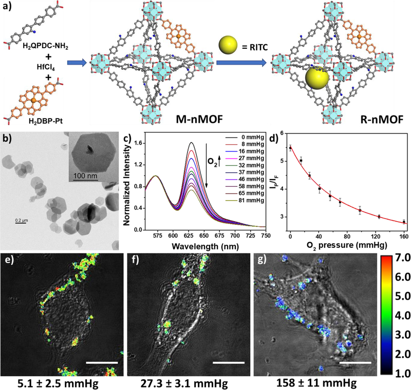
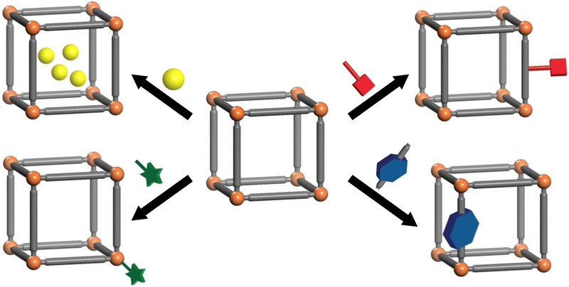
Nanotechnology has played an important role in drug delivery and biomedical imaging over the past two decades. In particular, nanoscale metal-organic frameworks (nMOFs) are emerging as an important class of biomedically relevant nanomaterials due to their high porosity, multifunctionality, and biocompatibility. The high porosity of nMOFs allows for the encapsulation of exceptionally high payloads of therapeutic and/or imaging cargoes while the building blocks-both ligands and the secondary building units (SBUs)-can be utilized to load drugs and/or imaging agents via covalent attachment. The ligands and SBUs of nMOFs can also be functionalized for surface passivation or active targeting at overexpressed biomarkers. The metal ions or metal clusters on nMOFs also render them viable candidates as contrast agents for magnetic resonance imaging, computed tomography, or other imaging modalities. This review article summarizes recent progress on nMOF designs and their exploration in biomedical areas. First, the therapeutic applications of nMOFs, based on four distinct drug loading strategies, are discussed, followed by a summary of nMOF designs for imaging and biosensing. The review is concluded by exploring the fundamental challenges facing nMOF-based therapeutic, imaging, and biosensing agents. This review hopefully can stimulate interdisciplinary research at the intersection of MOFs and biomedicine.

Keywords: cancer therapy; imaging; metal-organic frameworks; nanomedicine; nanoparticles.


Figures

Figure 1
Figure 1
(a) Schematic illustration of the MIL-101(Fe) nMOF design, its targeted delivery, and anticancer process. (b) Confocal images showing tumor-specific cellular uptake of DOX@TTMOF at different pH. Dot plots (c) and mean fluorescence intensity (d) of quantitative flow cytometry analysis. Tumor volume (e) and body weight (f) changes in H-22 tumor-bearing mice after treatment. Reproduced with permission.[51] Copyright 2015 The Royal Society of Chemistry.
Figure 2
Figure 2
(a) Scheme showing the encapsulation of small molecules into ZIF-8 during nMOF growth. (b) Fluorescein release profiles in PBS (black squares) and pH 6.0 buffer solution (red circles). (c) TEM image of fluorescein-encapsulated nanospheres dispersed in PBS for one day. (d) Cell viability when incubated with micron-sized ZIF-8 (dark gray), 70 nm ZIF-8 (light gray), and CPT encapsulated ZIF-8 (white). (e) Cell viability when incubated with free CPT (dark gray), and CPT-encapsulated ZIF-8 (light gray) for 24 h. (f) Fluorescence microscopy images of cells incubated with 70 nm fluorescein-encapsulated ZIF-8. (g) Fe3O4@ZIF-8 nanospheres migrated to sides of a vial upon application of an external magnetic field; inset: TEM image of single Fe3O4@ZIF-8 nanosphere. Reproduced with permission.[53] Copyright 2014, American Chemical Society.
Figure 3
Figure 3
Schematic representation of the drug attachment and surface modification of Fe(III)-MIL-101 nMOFs. Reproduced with permission.[73] Copyright 2009, American Chemical Society.
Figure 4
Figure 4
(a) Schematic description of the synthesis of DBP-Hf or DBC-Hf and the singlet oxygen generation process. The structure of Hf12 SBU (b) and the idealized crystal structure of DBP-Hf viewed along the c axis (c) and the a axis (d). TEM (e) and high-resolution TEM (f) images of DBP-Hf showing nanoplate morphology. (g) TEM image of DBC-Hf. In vivo tumor regression after PDT treatment of DBP-Hf (h) and DBC-Hf (i) on different tumor-bearing mice models, along with the control groups. Black and red arrows refer to the time of injection and irradiation, respectively. Reproduced with permission.[108, 117] Copyright 2014 and 2015, American Chemical Society.
Figure 5
Figure 5
(a) Schematic presentation of combined PDT and immunotherapy by IDOi@TBC-Hf. PXRD (b) and TEM image (c) of the nMOFs. In vivo anticancer efficacy of PDT treated (d) and untreated (e) tumors showing that IDOi@TBC-Hf enabled PDT induced abscopal effects. Reproduced with permission.[118] Copyright 2016, American Chemical Society.
Figure 6
Figure 6
(a) Schematic presentation of siRNA/nMOF-Cis synthesis and drug loading. (b) TEM image of siRNA/nMOF-Cis nanoparticles. (c) Confocal microscopy image showing siRNA endosomal escape. (d) Gene silencing efficiency of siRNA/nMOF-Cis expressed as percentage of protein expression. (e) In vitro anticancer efficacy on SKOV-3 cells showing re-sensitization effect with siRNA/nMOF-Cis. Reproduced with permission.[89] Copyright 2014, American Chemical Society.
Figure 7
Figure 7
(a) Scheme showing the synthesis and functionalization of UCNP@Fe-MIL-101_NH2 nanostructures. (b) TEM image of UMPs nanoparticles with core-shell structure. (c) Upconversion emission spectra of UMP nanostructures. Inset is the photo of UMPs nanostructures dispersed in water under 980 nm diode excitation. (d) Relaxation rate R2 (1/T2) versus molar concentrations of UMPs nanostructures at room temperature using a 3T MRI scanner (Inset: T2-weighted MR images of UMPs with varied concentrations). Representative upconversion luminescence (e,f) and T2-MRI images (g,h) of subcutaneous KB tumor-bearing mice (tumor diameter: 8–10 mm) and dissected organs of the mice sacrificed 24 h after intravenous injection of UMP-FAs (targeted, e,g) and UMPs (non-targeted, f,h). 1, heart; 2, kidney; 3, lung; 4, liver; 5, spleen; 6, KB tumor. (i) Biodistribution of nanostructures in organs of the tumor-bearing mice 24h after intravenous injection of particles. (j) Biodistribution of intravenously injected UMPs nanostructures in different organs of mice at 0.5 h, 12 h, 24 h, 7 d, and 30 d. Reproduced with permission.[158] Copyright 2015, Wiley-VCH.
Figure 8
Figure 8
Schematic illustration of the 89Zr-UiO-66 nMOF formulation and its use in PET imaging and drug delivery. Reproduced with permission.[128] Copyright 2017, American Chemical Society.
Figure 9
Figure 9
(a) Scheme showing the nMOF synthesis and fluorophore attachment of R-nMOF. (b) TEM image of R-nMOF. (c) Emission spectra of R-nMOF in HBSS buffer under various oxygen partial pressures with excitation wavelength at 514 nm. (d) Calibration curve of the phosphorescence/fluorescence intensity of R-nMOF on CLSM under different oxygen partial pressures. Ratiometric luminescence imaging (λex=514 nm) of CT26 cells after incubation with R-nMOF under hypoxia (e), normoxia (f), and aerated (g) conditions. Scale bar: 10 μm. Reproduced with permission.[91] Copyright 2016, American Chemical Society.
Scheme 1
Scheme 1
Four common strategies for loading drugs into nMOFs (shown clockwise from top left): noncovalent encapsulation, conjugation to the linkers, use of therapeutics as linkers, and attachment to the SBUs.

References

    1. Eddaoudi M, Kim J, Rosi N, Vodak D, Wachter J, O’Keeffe M, Yaghi OM, Science 2002, 295, 469. - PubMed
    1. Suh MP, Park HJ, Prasad TK, Lim D-W, Chem. Rev 2011, 112, 782. - PubMed
    1. Sumida K, Rogow DL, Mason JA, McDonald TM, Bloch ED, Herm ZR, Bae T-H, Long JR, Chem. Rev 2011, 112, 724. - PubMed
    1. Li J-R, Sculley J, Zhou H-C, Chem. Rev 2011, 112, 869. - PubMed
    1. He Y, Zhou W, Qian G, Chen B, Chem. Soc. Rev 2014, 43, 5657. - PubMed