

Coupling Magnetically Induced Electric Fields to Neurons: Longitudinal and Transverse Activation
- PMID: 29972816
- PMCID: PMC6035313
- DOI: 10.1016/j.bpj.2018.06.004
Coupling Magnetically Induced Electric Fields to Neurons: Longitudinal and Transverse Activation
Abstract
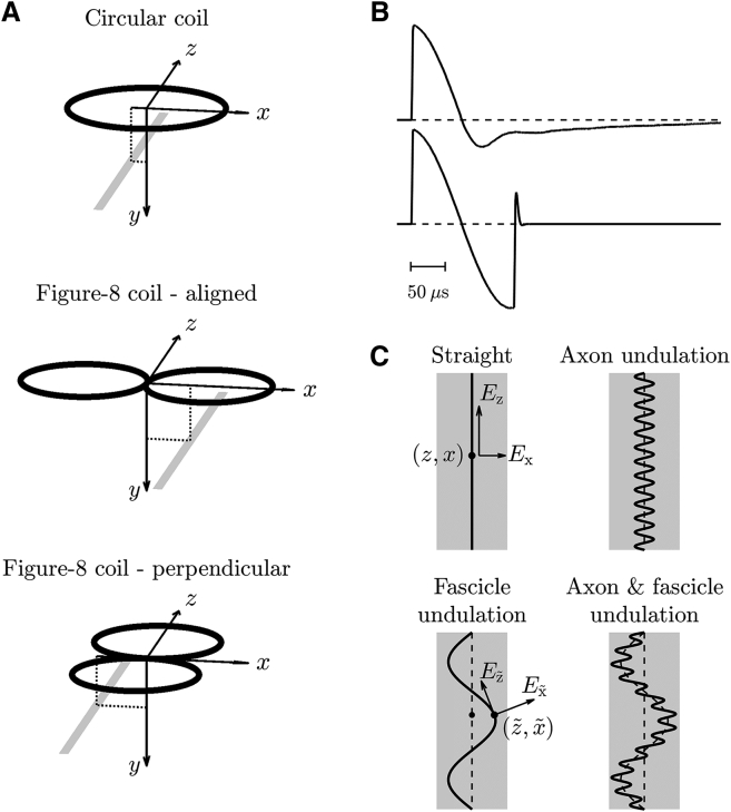
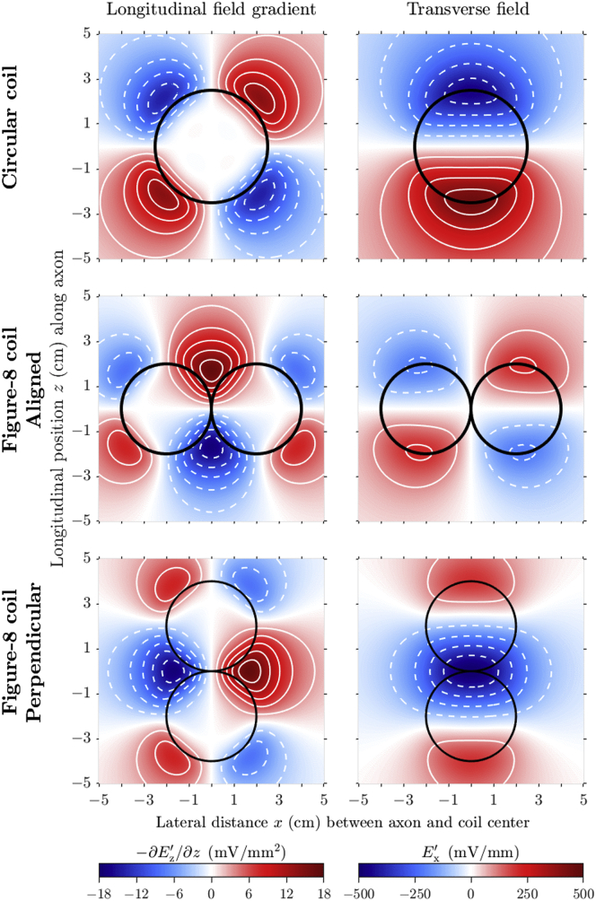
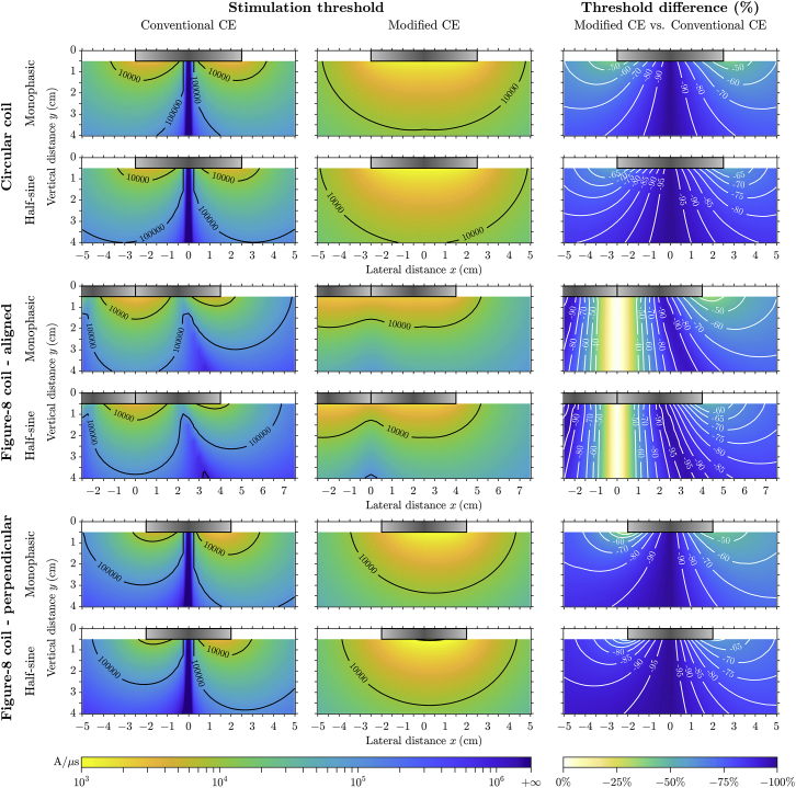
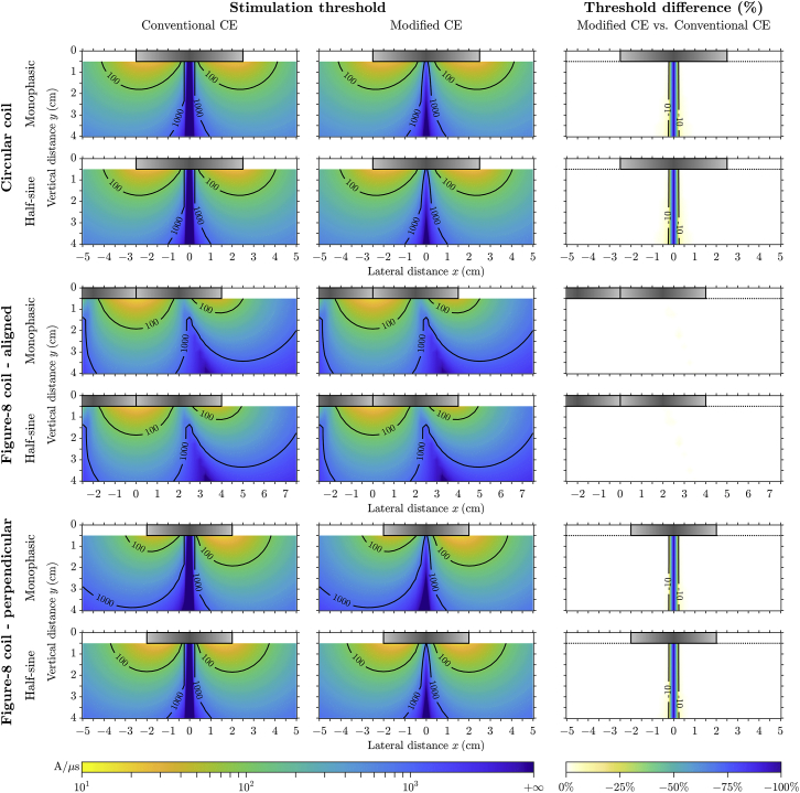
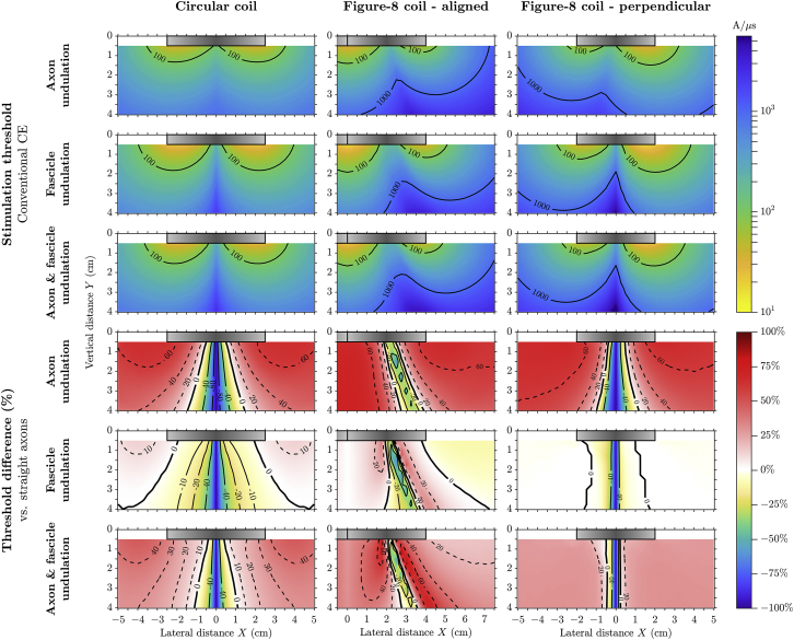
We present a theory and computational models to couple the electric field induced by magnetic stimulation to neuronal membranes. Based on the characteristics of magnetically induced electric fields and the modified cable equation that we developed previously, quasipotentials are derived as a simple and accurate approximation for coupling of the electric fields to neurons. The conventional and modified cable equations are used to simulate magnetic stimulation of long peripheral nerves by circular and figure-8 coils. Activation thresholds are obtained over a range of lateral and vertical coil positions for two nonlinear membrane models representing unmyelinated and myelinated straight axons and also for undulating myelinated axons. For unmyelinated straight axons, the thresholds obtained with the modified cable equation are significantly lower due to transverse polarization, and the spatial distributions of thresholds as a function of coil position differ significantly from predictions by the activating function. However, the activation thresholds of unmyelinated axons obtained with either cable equation are very high and beyond the output capabilities of conventional magnetic stimulators. For myelinated axons, threshold values are similar for both cable equations and within the range of magnetic stimulators. Whereas the transverse field contributes negligibly to the activation thresholds of myelinated fibers, axonal undulation can significantly increase or decrease thresholds depending on coil position. The analysis provides a rigorous theoretical foundation and implementation methods for the use of the cable equation to model neuronal response to magnetically induced electric fields. Experimentally observed stimulation with the electric fields perpendicular to the nerve trunk cannot be explained by transverse polarization and is likely due to nerve fiber undulation and other geometrical inhomogeneities.
Copyright © 2018 Biophysical Society. Published by Elsevier Inc. All rights reserved.
Figures
Similar articles
-
Modified cable equation incorporating transverse polarization of neuronal membranes for accurate coupling of electric fields.J Neural Eng. 2018 Apr;15(2):026003. doi: 10.1088/1741-2552/aa8b7c. J Neural Eng. 2018. PMID: 29363622 Free PMC article.
-
In vitro magnetic stimulation of pig phrenic nerve with transverse and longitudinal induced electric fields: analysis of the stimulation site.IEEE Trans Biomed Eng. 2009 Feb;56(2):500-12. doi: 10.1109/TBME.2008.2009929. Epub 2008 Dec 2. IEEE Trans Biomed Eng. 2009. PMID: 19272863
-
Transmembrane potential generated by a magnetically induced transverse electric field in a cylindrical axonal model.Med Biol Eng Comput. 2011 Jan;49(1):107-19. doi: 10.1007/s11517-010-0704-0. Epub 2010 Nov 10. Med Biol Eng Comput. 2011. PMID: 21063912
-
Electric field-induced effects on neuronal cell biology accompanying dielectrophoretic trapping.Adv Anat Embryol Cell Biol. 2003;173:III-IX, 1-77. doi: 10.1007/978-3-642-55469-8. Adv Anat Embryol Cell Biol. 2003. PMID: 12901336 Review.
-
From Maxwell's equations to the cable equation and beyond.Prog Biophys Mol Biol. 2004 May;85(1):71-116. doi: 10.1016/j.pbiomolbio.2003.08.001. Prog Biophys Mol Biol. 2004. PMID: 15050381 Review.
Cited by
-
Quasistatic approximation in neuromodulation.J Neural Eng. 2024 Jul 24;21(4):10.1088/1741-2552/ad625e. doi: 10.1088/1741-2552/ad625e. J Neural Eng. 2024. PMID: 38994790 Free PMC article. Review.
-
Effects of transcranial alternating current stimulation on spiking activity in computational models of single neocortical neurons.Neuroimage. 2022 Apr 15;250:118953. doi: 10.1016/j.neuroimage.2022.118953. Epub 2022 Jan 29. Neuroimage. 2022. PMID: 35093517 Free PMC article.
-
Rapid estimation of cortical neuron activation thresholds by transcranial magnetic stimulation using convolutional neural networks.Neuroimage. 2023 Jul 15;275:120184. doi: 10.1016/j.neuroimage.2023.120184. Epub 2023 May 23. Neuroimage. 2023. PMID: 37230204 Free PMC article.
-
Shielding effects of myelin sheath on axolemma depolarization under transverse electric field stimulation.PeerJ. 2018 Dec 3;6:e6020. doi: 10.7717/peerj.6020. eCollection 2018. PeerJ. 2018. PMID: 30533309 Free PMC article.
-
Boundary element fast multipole method for modeling electrical brain stimulation with voltage and current electrodes.J Neural Eng. 2021 Aug 19;18(4):10.1088/1741-2552/ac17d7. doi: 10.1088/1741-2552/ac17d7. J Neural Eng. 2021. PMID: 34311449 Free PMC article.
References
-
- Rotenberg A., Horvath J.C., Pascual-Leone A. Humana Press; New York: 2014. Transcranial Magnetic Stimulation.
-
- Lefaucheur J.P., André-Obadia N., Garcia-Larrea L. Evidence-based guidelines on the therapeutic use of repetitive transcranial magnetic stimulation (rTMS) Clin. Neurophysiol. 2014;125:2150–2206. - PubMed
-
- Evans B.A., Litchy W.J., Daube J.R. The utility of magnetic stimulation for routine peripheral nerve conduction studies. Muscle Nerve. 1988;11:1074–1078. - PubMed
-
- Goetz S.M., Weyh T., Herzog H.G. Coil design for neuromuscular magnetic stimulation based on a detailed 3-D thigh model. IEEE Trans. Magn. 2014;50:5100110.
Publication types
MeSH terms
Grants and funding
LinkOut - more resources
Full Text Sources
Other Literature Sources
Molecular Biology Databases
