

Review
doi: 10.1161/JAHA.117.007767.
Transcatheter Aortic and Mitral Valve-in-Valve Implantation Using the Edwards Sapien 3 Heart Valve
Affiliations
- PMID: 29982230
- PMCID: PMC6064864
- DOI: 10.1161/JAHA.117.007767
Item in Clipboard
Review
Transcatheter Aortic and Mitral Valve-in-Valve Implantation Using the Edwards Sapien 3 Heart Valve
J Am Heart Assoc.
.
No abstract available
Keywords: Sapien 3; aortic valve implantation; aortic valve replacement; mitral valve; transcatheter aortic valve replacement; transcatheter mitral valve replacement; transcatheter valve implantation; valve‐in‐valve.
Figures

Surgical bioprosthesis sizing terms. A schematic representation of a cross‐section through a failed bioprosthetic valve is shown. Valve size measurements may be defined in a number of ways. Manufacturer label size is variable and does not usually indicate the internal diameter of the valve. S‐ID is used to indicate the inner diameter of the valve struts/frame, including overlying fabric. T‐ID accounts for the leaflets and sutures (represented in blue) sewn within the stent frame, whereas CT ‐ID also includes any accumulated pannus or calcification (represented in orange) within the degenerated bioprosthesis. CT‐ID indicates computed‐tomography inner diameter; S‐ID, stent inner diameter; T‐ID, true inner diameter.

Algorithm for determining the choice of S3 THV size. This simplified flow chart can be used during VIV TAVR to facilitate selection of the S3 THV size, and guide when balloon sizing may be appropriate. A minimum of 1 mm oversizing is required in order to ensure adequate anchoring of the S3 THV within the bioprosthesis. Use of the smallest possible THV reduces the risk of excessive flaring of the outflow portion of the stent frame. N.B. In small bioprosthetic valves (label size ≤21), the risk of patient–prosthesis mismatch is high after VIV TAVR . High‐pressure balloon postdilatation with bioprosthetic valve fracture may enable implantation of a larger size THV with improved transvalvular gradient. CT‐ID indicates computed‐tomography inner diameter; S3, Sapien 3; THV, transcatheter heart valve; T‐ID, true inner diameter; VIV TAVR, valve‐in‐valve transcatheter aortic valve replacement.

Central regurgitation after extensive oversizing of a 26‐mm S3 THV within a St. Jude Epic 27‐mm bioprosthesis in the mitral position. Although the T‐ID of the 27‐mm St. Jude Epic is 22.5 mm, a mean preoperative CT ‐ID of 18.2 mm was measured in this degenerated bioprosthesis (Panel A1). The VIV app recommends use of a 26‐mm S3 THV ; however, deployment resulted in underexpansion of the device within the bioprosthesis and extensive flaring of the outflow portion of the frame (Panels B1 to B4), associated with central regurgitation (Panels C1 and C2). CT‐ID indicates computed‐tomography inner diameter; S3, Sapien 3; THV, transcatheter heart valve; T‐ID, true inner diameter; VIV, valve‐in‐valve.

Mitral VIV . S3 valve choice based on CT ‐ID , balloon‐sizing, and tug‐test. Case of S3 26‐mm valve inside an Epic 31 mm (St. Jude Medical) with a T‐ID of 26.5 mm. The VIV Mitral App recommends implanting a S3 29‐mm valve. Based on the CT ‐ID of 18.7 mm and balloon‐sizing and tug‐test with a 25‐mm balloon, the decision was to deploy a 26‐mm S3 valve with nominal filling volume. A1. Epic 31‐mm (St. Jude Medical) valve: CT ‐ID was measured at 18.7 mm. A2. Aorto‐mitral angle: 138 degrees. B1. Coplanar view of the mitral valve. B2. Balloon‐sizing and tug‐test with a 25‐mm Edwards balloon. B3. S3 26‐mm positioning towards left ventricle because of expected underdeployment. B4. S3 26‐mm implantation result with a flared frame on the ventricular side. B5. Left ventricular angiography to assess for MV regurgitation. B6. S3 26‐mm “round” deployment. CT‐ID indicates computed‐tomography inner diameter; MV, mitral valve; S3, Sapien 3; T‐ID, true inner diameter; VIV, valve‐in‐valve.

Examples of using high‐pressure postdilatation to optimize THV deployment in small bioprosthetic valves. Contrast and brightness are adjusted to minimize blooming artifact. A. Edwards S3 20‐mm THV inside a Perimount 21 valve (true inner diameter 19 mm). A1. Stent inner diameter of the Perimount sewing ring measured on the baseline CT —18.1×18.9 mm. A2. Twenty‐mm S3 angiographic appearance after deployment. Note the waist appearance at the level of the sewing ring. A3. Angiographic appearance of the 20‐mm S3 after postdilatation with a 20‐mm True Dilatation balloon (Bard) to 16 atmospheres showing improved device expansion within the bioprosthesis. A4. Stent inner diameter of the Perimount sewing ring on CT after high‐pressure postdilatation showing increased dimensions of 18.9×20.1 mm. A residual transvalvular mean gradient of 12 mm Hg was observed on echocardiography. B. Edwards S3 23‐mm THV inside a Perimount 21 valve (true inner diameter 19 mm). B1. Stent inner diameter of the Perimount sewing ring measured on the baseline CT —18.4×20.2 mm. B2. Twenty‐three‐mm S3 angiographic appearance after deployment. Note the mild waist appearance at the level of the sewing ring. B3. Angiographic appearance of the 23‐mm S3 after postdilatation with a 22‐mm Atlas Gold balloon (Bard) to 20 atmospheres showing improved device expansion within the bioprosthesis. B4. Stent inner diameter of the Perimount sewing ring on CT after high‐pressure postdilatation showing increased dimensions of 20.2×20.1 mm. A residual transvalvular mean gradient of 18 mm Hg was observed on echocardiography. CT indicates computed tomography; S3, Sapien 3; THV , transcatheter heart valve.

Balloon‐sizing, tug‐test, and S3 overdeployment. Case of S3 23‐mm valve inside a Mitroflow 27‐mm valve with a T‐ID of 23 mm. The VIV Aortic App recommends implanting a S3 26‐mm valve in this circumstance. Planned overdeployment of a S3 23‐mm (+2 mL in deployment‐balloon) THV after balloon‐sizing and tug‐test with a 23‐mm balloon. A. Coplanar View. B. Balloon sizing and the tug‐test show that the coronary arteries are not obstructed, and the balloon is fixed in the bioprosthetic surgical valve. C. Placement of the S3 23‐mm middle marker is at the bottom of the suture ring of the bioprosthetic surgical valve (“low position”). D. Implantation result shows no aortic insufficiency with a peak‐to‐peak gradient of 5 mm Hg across this valve. S3 indicates Sapien 3; THV , transcatheter heart valve; T‐ID , true inner diameter; VIV , valve‐in‐valve.
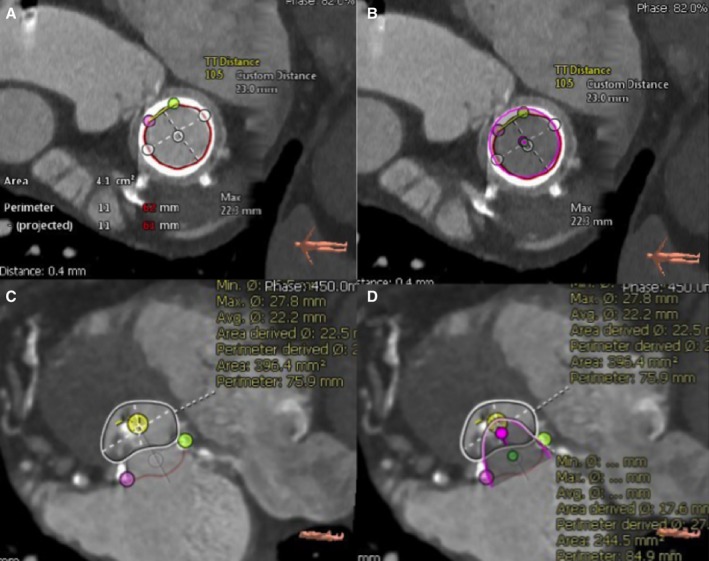
Mitral annular area and neo‐LVOT area measurements. A, Cardiac computed tomography–based measurement of the mitral internal annular area using 3Mensio Structural Heart Mitral Workflow version 8.1 (Pie Medical Imaging, Maastricht, the Netherlands). B, Short‐axis view of the mitral bioprosthesis with a 23‐mm virtual valve in place (pink circle). C, Measurement of the LVOT tract area in systole in short‐axis (white circle) view using 3Mensio Structural Heart Mitral Workflow version 8.1 (Pie Medical Imaging, Maastricht, the Netherlands). D, Measurement of the remaining LVOT area in short axis (white circle) after placement of the virtual transcatheter heart valve (pink). The remaining space in the LVOT after placement of the virtual valve is the neo‐LVOT . A neo‐LVOT area of 250 mm2 or larger is associated with a low risk of LVOT obstruction. LVOT indicates left ventricular outflow tract.

Coplanar alignment of stented surgical bioprosthetic valves. Varying alignment of the coplanar view: A. Overlap of struts, B. Struts in 1 line, C. Stent top markers in 1 line. Stented surgical valves can be aligned based on the top markers/struts of the valve, the suture ring, or angiographically at the nadir of the cusps of the leaflets. The dotted red line represents the suture ring or the stent strut tips of the surgical valve. The length of the middle marker is 3 mm on the S3 THV . The figure depicts the accurate placement of the S3 THV along the dotted red line: 1, Predetermined overexpansion (“low position”); 2, Predetermined nominal deployment (3–5 mm above the suture ring); 3, Predetermined underexpansion (“high position”). S3 indicates Sapien 3; THV , transcatheter heart valve.
References
-
- Piazza N, Bleiziffer S, Brockmann G, Hendrick R, Deutsch MA, Opitz A, Mazzitelli D, Tassani‐Prell P, Schreiber C, Lange R. Transcatheter aortic valve implantation for failing surgical aortic bioprosthetic valve: from concept to clinical application and evaluation (part 1). JACC Cardiovasc Interv. 2011;4:721–732. - PubMed
-
- Webb JG, Dvir D. Transcatheter aortic valve replacement for bioprosthetic aortic valve failure: the valve‐in‐valve procedure. Circulation. 2013;127:2542–2550. - PubMed
-
- Bapat V. ViV Aortic App. 2009. Available at: http://www.ubqo.com/viv.
-
- Gurvitch R, Cheung A, Ye J, Wood DA, Willson AB, Toggweiler S, Binder R, Webb JG. Transcatheter valve‐in‐valve implantation for failed surgical bioprosthetic valves. J Am Coll Cardiol. 2011;58:2196–2209. - PubMed
-
- Bapat V, Mydin I, Chadalavada S, Tehrani H, Attia R, Thomas M. A guide to fluoroscopic identification and design of bioprosthetic valves: a reference for valve‐in‐valve procedure. Catheter Cardiovasc Interv. 2013;81:853–861. - PubMed
Publication types
MeSH terms
LinkOut - more resources
Full Text Sources
Other Literature Sources
