Review
. 2018 Oct;5(5):965-976.
doi: 10.1002/ehf2.12315. Epub 2018 Jul 9.

Rationale and design of the randomized multicentre His Optimized Pacing Evaluated for Heart Failure (HOPE-HF) trial

Affiliations
Review

Rationale and design of the randomized multicentre His Optimized Pacing Evaluated for Heart Failure (HOPE-HF) trial

Daniel Keene et al. ESC Heart Fail. 2018 Oct.

Abstract

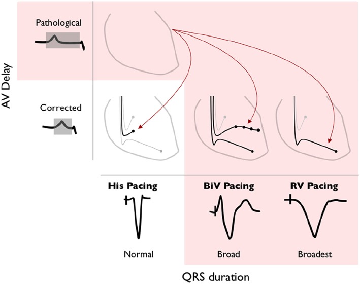
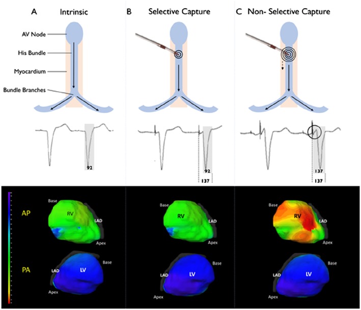
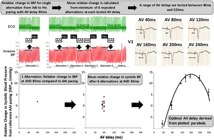
Aims: In patients with heart failure and a pathologically prolonged PR interval, left ventricular (LV) filling can be improved by shortening atrioventricular delay using His-bundle pacing. His-bundle pacing delivers physiological ventricular activation and has been shown to improve acute haemodynamic function in this group of patients. In the HOPE-HF (His Optimized Pacing Evaluated for Heart Failure) trial, we are investigating whether these acute haemodynamic improvements translate into improvements in exercise capacity and heart failure symptoms.

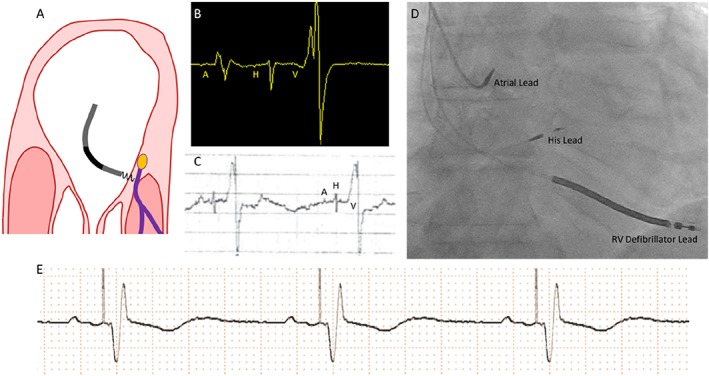
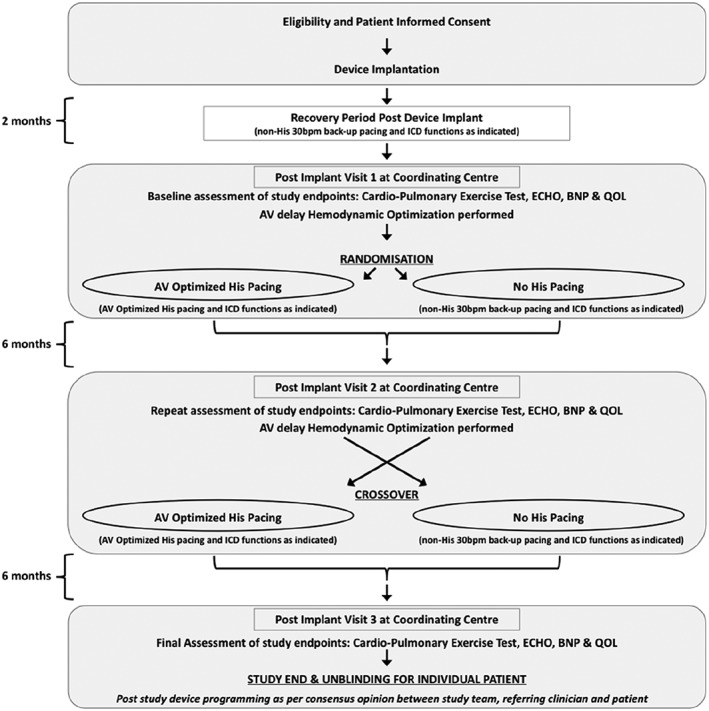
Methods and results: This multicentre, double-blind, randomized, crossover study aims to randomize 160 patients with PR prolongation (≥200 ms), LV impairment (EF ≤ 40%), and either narrow QRS (≤140 ms) or right bundle branch block. All patients receive a cardiac device with leads positioned in the right atrium and the His bundle. Eligible patients also receive a defibrillator lead. Those not eligible for implantable cardioverter defibrillator have a backup pacing lead positioned in an LV branch of the coronary sinus. Patients are allocated in random order to 6 months of (i) haemodynamically optimized dual chamber His-bundle pacing and (ii) backup pacing only, using the non-His ventricular lead. The primary endpoint is change in exercise capacity assessed by peak oxygen uptake. Secondary endpoints include change in ejection fraction, quality of life scores, B-type natriuretic peptide, daily patient activity levels, and safety and feasibility assessments of His-bundle pacing.

Conclusions: Hope-HF aims to determine whether correcting PR prolongation in patients with heart failure and narrow QRS or right bundle branch block using haemodynamically optimized dual chamber His-bundle pacing improves exercise capacity and symptoms. We aim to complete recruitment by the end of 2018 and report in 2020.

Keywords: Atrioventricular delay; Heart failure; His-bundle pacing; Optimization.


Figures

Figure 1
Figure 1
Potential pacing methods for atrioventricular (AV) delay optimization. His‐bundle pacing, biventricular (BiV) pacing, and right ventricular (RV) pacing are all potential methods for shortening a pathologically long AV delay. His‐bundle pacing does not prolong left ventricular activation time, when applied to patients with a narrow QRS duration, whereas BiV pacing and RV pacing prolong left ventricular activation time.
Figure 2
Figure 2
(A) Intended area within right atrium for implantation of the His pacing lead. The target area is where the non‐branching part of the His bundle sits above the tricuspid valve on the right atrial—left ventricular part of the membranous septum. (B) Appearance of a single cardiac cycle recorded on an EP system, from a well‐positioned His lead. Note that the atrial component (A) is less than half the size of the ventricular component (V). There is a His signal (H) between the two. This appearance suggests a favourable location. (C) The electrogram can also be displayed using the Pace–Sense Analyser. It is advisable to measure initially a unipolar signal utilizing the atrial channel with a gain setting of 0.05 mV/mm and a sweep speed of 50–100 mm/s. The ventricular channel is not sufficiently sensitive to detect His potentials. (D) This anterior–posterior projection radiographic image shows the typical anatomical location for the His lead (labelled). (E) Rhythm strip showing successful His‐bundle pacing. RV, right ventricular.
Figure 3
Figure 3
Differences between selective and non‐selective His pacing. (A) Normal intrinsic conduction. The electrocardiographic imaging (Medtronic Inc., Minneapolis, MN, USA) activation map shows rapid activation (each ventricle has homogenous colouring). (B) Selective His‐bundle pacing. Ventricular activation occurs solely via the His‐Purkinje system, giving a normal QRS and normal activation map. The middle panel shows the short delay between the pacing spike and the onset of ventricular activation. (C) Non‐selective His‐bundle pacing, during which ventricular activation occurs via both local myocardial capture [seen as early activation in right ventricle (RV) (red colour)] and activation via the His‐Purkinje system. Left ventricular (LV) activation time and pattern is the same as during intrinsic activation and with selective His pacing because activation of the LV occurs via the His‐Purkinje system. AP, anterior‐posterior orientation; LAD, left anterior descending; PA, posterior‐anterior orientation.
Figure 4
Figure 4
Patient study flow chart (AV, atrioventricular; BNP, B‐type natriuretic protein; ICD, implantable cardioverter defibrillator; QOL, quality of life).
Figure 5
Figure 5
Atrioventricular (AV) delay optimization protocol. The relative change in systolic blood pressure (SBP) between 8 beats of AAI pacing and 8 beats of dual chamber atrial synchronous–His pacing at a given atrioventricular delay (AVD) is determined [AV delay = 80 ms in this example (top left)]. This is a single alternation (plotted bottom left). A minimum of six alternations are made for each AVD (middle sections top and bottom). This process is repeated for each AV delay between 40 and 320 ms (less if intrinsic AV conduction occurs before 320 ms). The optimal AV delay is then derived from the plotted parabola (bottom right). In this example, the optimal AV delay was 160 ms. BP, blood pressure; ECG, electrocardiogram.

References

    1. Stockburger M, Moss AJ, Klein HU, Zareba W, Goldenberg I, Biton Y, McNitt S, Kutyifa V. Sustained clinical benefit of cardiac resynchronization therapy in non‐LBBB patients with prolonged PR‐interval: MADIT‐CRT long‐term follow‐up. Clin Res Cardiol 2016; 105: 944–952. - PubMed
    1. Kutyifa V, Stockburger M, Daubert JP, Holmqvist F, Olshansky B, Schuger C, Klein H, Goldenberg I, Brenyo A, McNitt S, Merkely B, Zareba W, Moss AJ. PR interval identifies clinical response in patients with non‐left bundle branch block: a Multicenter Automatic Defibrillator Implantation Trial‐Cardiac Resynchronization Therapy substudy. Circ Arrhythm Electrophysiol 2014; 7: 645–651. - PubMed
    1. Salden FCWM, Kutyifa V, Stockburger M, Prinzen FW, Vernooy K. Atrioventricular dromotropathy: evidence for a distinctive entity in heart failure with prolonged PR interval? Europace 2017. 10.1093/europace/eux207. - DOI - PubMed
    1. Ploux S, Eschalier R, Whinnett ZI, Lumens J, Derval N, Sacher F, Hocini M, Jaïs P, Dubois R, Ritter P, Haïssaguerre M, Wilkoff BL, Francis DP, Bordachar P. Electrical dyssynchrony induced by biventricular pacing: implications for patient selection and therapy improvement. Heart Rhythm 2015; 12: 782–791. - PubMed
    1. Nikolaidou T, Pellicori P, Zhang J, Kazmi S, Goode KM, Cleland JG, Clark AL. Prevalence, predictors, and prognostic implications of PR interval prolongation in patients with heart failure. Clin Res Cardiol 2017; 107: 108–119. - PMC - PubMed

Publication types

MeSH terms