

MR Performance in the Presence of a Radio Frequency-Penetrable Positron Emission Tomography (PET) Insert for Simultaneous PET/MRI
- PMID: 29993864
- PMCID: PMC6195123
- DOI: 10.1109/TMI.2018.2815620
MR Performance in the Presence of a Radio Frequency-Penetrable Positron Emission Tomography (PET) Insert for Simultaneous PET/MRI
Abstract
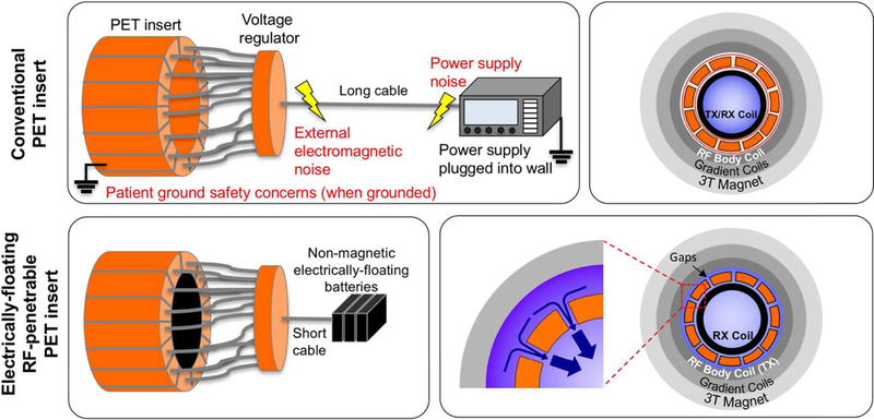
Despite the great promise of integrated positron emission tomography (PET)/magnetic resonance (MR) imaging to add molecular information to anatomical and functional MR, its potential impact in medicine is diminished by a very high cost, limiting its dissemination. An RF-penetrable PET ring that can be inserted into any existing MR system has been developed to address this issue. Employing optical signal transmission along with battery power enables the PET ring insert to electrically float with respect to the MR system. Then, inter-modular gaps of the PET ring allow the RF transmit field from the standard built-in body coil to penetrate into the PET fields-of-view (FOV) with some attenuation that can be compensated for. MR performance, including RF noise, magnetic susceptibility, RF penetrability through and $B_{1}$ uniformity within the PET insert, and MR image quality, were analyzed with and without the PET ring present. The simulated and experimentally measured RF field attenuation factors with the PET ring present were -2.7 and -3.2 dB, respectively. The magnetic susceptibility effect (0.063 ppm) and noise emitted from the PET ring in the MR receive channel were insignificant. $B_{1}$ homogeneity of a spherical agar phantom within the PET ring FOV dropped by 8.4% and MR image SNR was reduced by 3.5 and 4.3 dB with the PET present for gradient-recalled echo and fast-spin echo, respectively. This paper demonstrates, for the first time, an RF-penetrable PET insert comprising a full ring of operating detectors that achieves simultaneous PET/MR using the standard built-in body coil as the RF transmitter.
Figures


Similar articles
-
Performance evaluation of RF coils integrated with an RF-penetrable PET insert for simultaneous PET/MRI.Magn Reson Med. 2019 Feb;81(2):1434-1446. doi: 10.1002/mrm.27444. Epub 2018 Sep 9. Magn Reson Med. 2019. PMID: 30260501 Free PMC article.
-
Simultaneous PET/MR imaging with a radio frequency-penetrable PET insert.Med Phys. 2017 Jan;44(1):112-120. doi: 10.1002/mp.12031. Med Phys. 2017. PMID: 28102949 Free PMC article.
-
Geometry optimization of electrically floating PET inserts for improved RF penetration for a 3 T MRI system.Med Phys. 2018 Oct;45(10):4627-4641. doi: 10.1002/mp.13132. Epub 2018 Sep 19. Med Phys. 2018. PMID: 30118140
-
Hybrid Positron Emission Tomography/Magnetic Resonance Imaging: Challenges, Methods, and State of the Art of Hardware Component Attenuation Correction.Invest Radiol. 2016 Oct;51(10):624-34. doi: 10.1097/RLI.0000000000000289. Invest Radiol. 2016. PMID: 27175550 Review.
-
Attenuation Correction for Magnetic Resonance Coils in Combined PET/MR Imaging: A Review.PET Clin. 2016 Apr;11(2):151-60. doi: 10.1016/j.cpet.2015.10.004. Epub 2015 Nov 27. PET Clin. 2016. PMID: 26952728 Free PMC article. Review.
Cited by
-
3D Auto-Context-Based Locality Adaptive Multi-Modality GANs for PET Synthesis.IEEE Trans Med Imaging. 2019 Jun;38(6):1328-1339. doi: 10.1109/TMI.2018.2884053. Epub 2018 Nov 29. IEEE Trans Med Imaging. 2019. PMID: 30507527 Free PMC article.
-
Performance study of a radio-frequency field-penetrable PET insert for simultaneous PET/MRI.IEEE Trans Radiat Plasma Med Sci. 2018 Sep;2(5):422-431. doi: 10.1109/TRPMS.2018.2852686. Epub 2018 Jul 3. IEEE Trans Radiat Plasma Med Sci. 2018. PMID: 30911706 Free PMC article.
-
Evaluation of the radiofrequency performance of a wide-bore 1.5 T positron emission tomography/magnetic resonance imaging body coil for radiotherapy planning.Phys Imaging Radiat Oncol. 2020 Dec 23;17:13-19. doi: 10.1016/j.phro.2020.12.002. eCollection 2021 Jan. Phys Imaging Radiat Oncol. 2020. PMID: 33898772 Free PMC article.
-
Performance evaluation of RF coils integrated with an RF-penetrable PET insert for simultaneous PET/MRI.Magn Reson Med. 2019 Feb;81(2):1434-1446. doi: 10.1002/mrm.27444. Epub 2018 Sep 9. Magn Reson Med. 2019. PMID: 30260501 Free PMC article.
-
Design and system evaluation of a dual-panel portable PET (DP-PET).EJNMMI Phys. 2021 Jun 12;8(1):47. doi: 10.1186/s40658-021-00392-5. EJNMMI Phys. 2021. PMID: 34117943 Free PMC article.
References
-
- Wehrl HF, Sauter AW, Divine MR, and Pichler BJ, “Combined PET/MR: A Technology Becomes Mature,” J Nucl Med, vol. 56, no. 2, pp. 165–168, 2015 - PubMed
-
- Pichler BJ, Judenhofer MS, and Pfannenberg C, “Multimodal Imaging Approaches: PET/CT and PET/MRI,” in Handb Exp Pharmacol, vol. 185, pp. 109–132, 2008 - PubMed
-
- Delso G, ter Voert E, de Galiza Barbosa F, and Veit-Haibach P, “Pitfalls and Limitations in Simultaneous PET/MRI,” Semin Nucl Med, vol. 45, no. 6, pp. 552–559, 2015 - PubMed
-
- Disselhorst JA, Bezrukov I, Kolb A, Parl C, and Pichler BJ, “Principles of PET/MR Imaging,” J Nucl Med, vol. 55 (supplement 2), pp. 2S–10S, 2014 - PubMed
Publication types
MeSH terms
Grants and funding
LinkOut - more resources
Full Text Sources
Other Literature Sources
Medical
Miscellaneous
