Review
. 2018 Jul 10;11(7):1175.
doi: 10.3390/ma11071175.

Review: Modes and Processes of Severe Plastic Deformation (SPD)

Affiliations
Review

Review: Modes and Processes of Severe Plastic Deformation (SPD)

Vladimir Segal. Materials (Basel). .

Abstract

In this review, severe plastic deformation (SPD) is considered as a materials processing technology. The deformation mode is the principal characteristic differentiating SPD techniques from common forming operations. For large plastic strains, deformation mode depends on the distribution of strain rates between continuum slip lines and can be varied from pure shear to simple shear. A scalar, invariant, and dimensionless coefficient of deformation mode is introduced as a normalized speed of rigid rotation. On this basis, simple shear provides the optimal mode for structure modification and grain refinement, whereas pure shear is “ideal” for forming operations. Special experiments and SPD practice confirm this conclusion. Various techniques of SPD are classified and described in accordance with simple shear realization or approximation. It is shown that correct analyses of the processing mechanics and technological parameters are essential for the comparison of SPD techniques and the development of effective industrial technologies.

Keywords: SPD techniques; mode deformation; severe plastic deformation (SPD); simple shear and pure shear; structure modification.


Conflict of interest statement

The author declare no conflicts of interest.

Figures

Figure 1
Figure 1
The element distortion along slip lines: (a) general case; (b) pure shear; (c) simple shear.
Figure 2
Figure 2
Moore’s circles with rotation (a) and in the limit cases of pure shear and simple shear (b).
Figure 3
Figure 3
Texture strength (OD index) of Al0.5%Cu alloy versus effective strains after: 1—rolling of the original material; 2—ECAE of the original material; 3—rolling of the UFG material; 4—ECAE of the UFG material.
Figure 4
Figure 4
Ultimate tensile strength (σB) (solid lines) and hardening coefficient K (dashed lines) of Al0.5%Cu alloy versus effective strains ε after: 1—rolling of the original material; 2—ECAE of the original material; 3—rolling of the UFG material; 4-ECAE of the UFG material.
Figure 5
Figure 5
Shear band localization during ECAE (a) and rolling (b) of Al0.5%Cu alloy (SB-shear bands; RD-rolling direction).
Figure 6
Figure 6
Microstructures of pure Al (99.9992%) after dynamic recrystallization induced by ECAE (a) and rolling (b) with effective strain of ε = 4.6.
Figure 7
Figure 7
Dynamically recrystallized area (%) (solid lines) and hardness HB (dashed lines) of pure Al (99.9992%) versus effective strains ε: 1—rolling; 2—ECAE, Route D (BC); 3—ECAE, Route A; 4—ECAE, Route C; 5—rolling; 6—ECAE.
Figure 8
Figure 8
Transition from pure shear to simple shear after flow localization during frictionless upsetting (a) and simple shear of thin layer (b).
Figure 9
Figure 9
Simple shear along line of velocity discontinuity.
Figure 10
Figure 10
Simple shear processing during extrusion: (a) slip line field for extrusion through smooth 30° die with an area reduction of 50%; (b) distribution of accumulated shear (1) and shears along lines of velocity discontinuity (2) through section h.
Figure 11
Figure 11
Slip line solutions for surface SPD: (a) contact sliding; (b) contact rolling; (c) contact penetration.
Figure 12
Figure 12
Slip line solution around an asperity during friction SPD.
Figure 13
Figure 13
Schematic of high-pressure torsion (HPT): (a) fully constrained HPT; (b) hardening diagrams; (c) HPT of long samples.
Figure 14
Figure 14
Friction SPD: (a) High-pressure tube twisting; (b) Cone-cone torsion; (c) High-pressure sliding.
Figure 15
Figure 15
Simple shear SPD: (a) Equal-channel angular extrusion/pressing (ECAE/ECAP); (b) Continuous ECAE-conform; (c) Semi-continuous incremental—ECAP.
Figure 16
Figure 16
Simple shear SPD: (a) Multi-pass ECAE in the rotary die; (b) Multi-turn ECAE; (c) Tubular channel angular pressing.
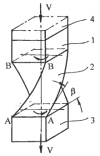
Figure 17
Figure 17
Twist-extrusion (TE).
Figure 18
Figure 18
Simple shear imitation: (a) Equal-channel angular drawing; (b) Supposed shear zones during constrained groove pressing (CGP); (c) Actual tensile–bending zones during CGP.
Figure 19
Figure 19
Equal-channel angular swaging (a) and “simple shear extrusion” (b).
Figure 20
Figure 20
Plastic zones during two-directional plane forging: (a) Original position; (b) Intermediate position; (c) Final position.
Figure 21
Figure 21
SPD by ordinary forming operations: (a) First step of backward extrusion; (b) Second step of backward extrusion; (c) Cyclic extrusion-compression.
Figure 22
Figure 22
Equal channel forward extrusion.
Figure 23
Figure 23
“Pure shear extrusion”.

References

    1. Kulhman-Wilsdorf D. Theory of plastic deformation-properties of low-energy dislocation structures. Mater. Sci. Eng. A. 1989;113:1–41. doi: 10.1016/0921-5093(89)90290-6. - DOI
    1. Hansen N. Cold deformation microstrustures. Mater. Sci. Technol. 1990;11:1039–1047. doi: 10.1179/mst.1990.6.11.1039. - DOI
    1. Bridgman P.W. Studies in Large Plastic Deformation and Fracture. McGraw-Hill; New York, NY, USA: 1952. p. 362.
    1. Valiev R.Z., Islamgaliev R.K., Aleksandrov I.V. Bulk nanostructured materials from severe plastic deformation. Prog. Mater. Sci. 2000;45:103–189. doi: 10.1016/S0079-6425(99)00007-9. - DOI
    1. Mayers M.A., Mishra M., Benson D.J. Mechanical properties of nanocrystalline materials. Prog. Mater. Sci. 2006;51:427–556. doi: 10.1016/j.pmatsci.2005.08.003. - DOI

LinkOut - more resources