Review
. 2018 Jul 30;47(15):5646-5683.
doi: 10.1039/c7cs00263g.

Microfluidic fabrication of microparticles for biomedical applications

Affiliations
Review

Microfluidic fabrication of microparticles for biomedical applications

Wen Li et al. Chem Soc Rev. .

Abstract

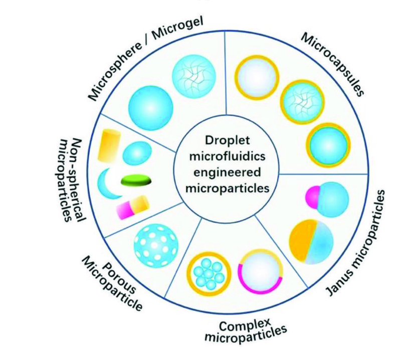
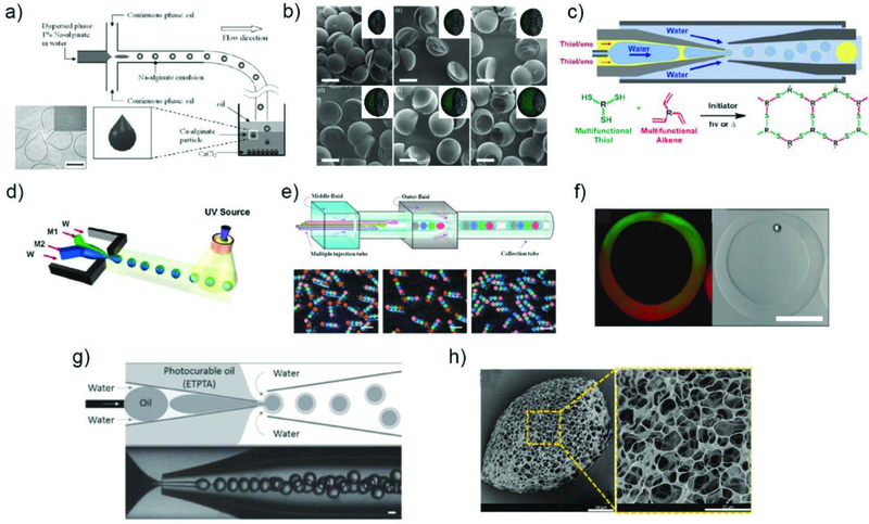
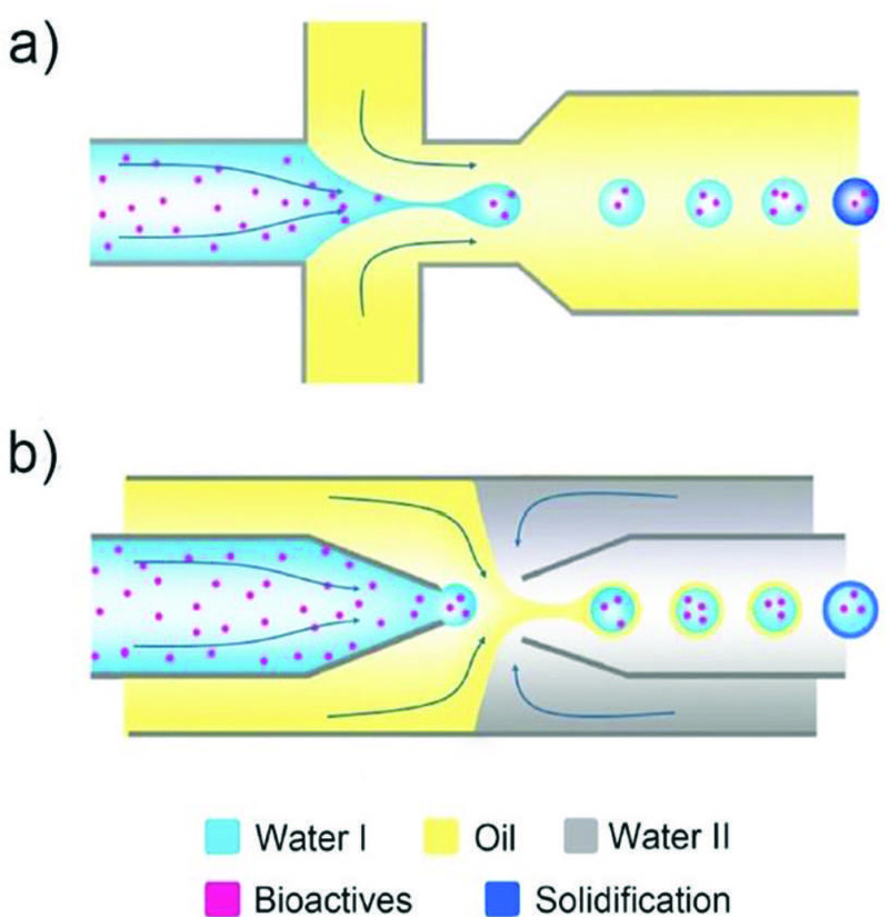
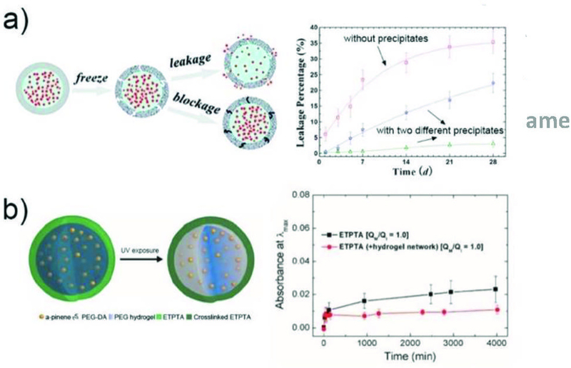
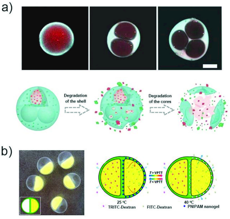
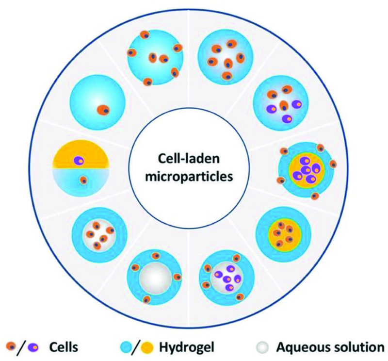
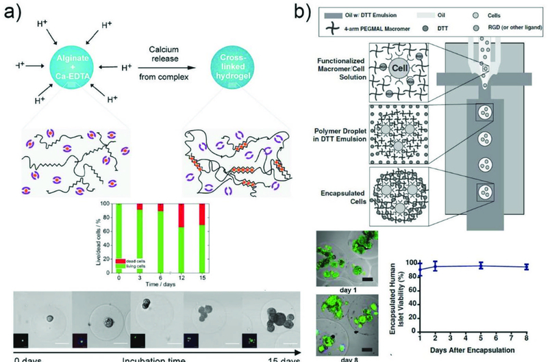
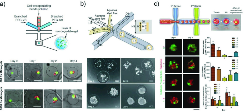
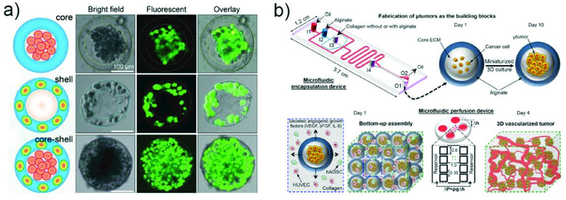
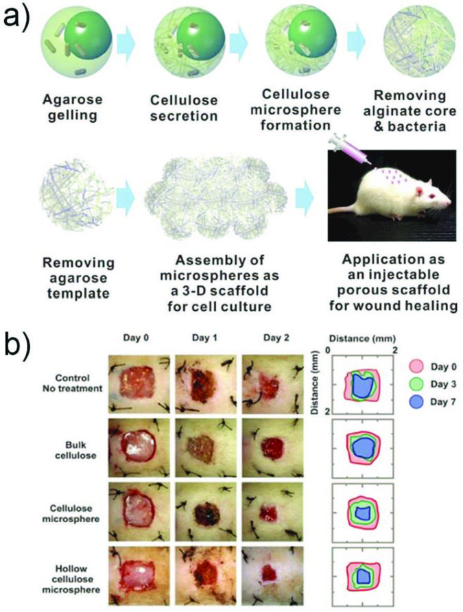
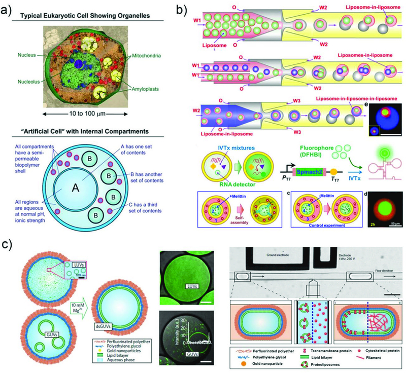
Droplet microfluidics offers exquisite control over the flows of multiple fluids in microscale, enabling fabrication of advanced microparticles with precisely tunable structures and compositions in a high throughput manner. The combination of these remarkable features with proper materials and fabrication methods has enabled high efficiency, direct encapsulation of actives in microparticles whose features and functionalities can be well controlled. These microparticles have great potential in a wide range of bio-related applications including drug delivery, cell-laden matrices, biosensors and even as artificial cells. In this review, we briefly summarize the materials, fabrication methods, and microparticle structures produced with droplet microfluidics. We also provide a comprehensive overview of their recent uses in biomedical applications. Finally, we discuss the existing challenges and perspectives to promote the future development of these engineered microparticles.


Conflict of interest statement

Conflicts of interest

There are no conflicts to declare.

Figures

Fig. 1
Fig. 1
a) Schematic illustration of various channel geometries including cross-flow, co-flow, and flow-focusing. b) Schematic illustration of a step-emulsification channel arranged with four parallelized drop markers. The drop breakup occurs at the step between the nozzle and the continuous phase channel. Reprinted with permission from ref. . Copyright 2016, John Wiley & Sons, Inc.
Fig. 2
Fig. 2
a) Schematic illustration of the millipede device and the drops produced. Reprinted with permission from ref. . Copyright 2016, The Royal Society of Chemistry. b) Droplet clearance from the nozzle exits in PDMS volcano device. Reprinted with permission from ref. . Copyright 2018, The Royal Society of Chemistry. c) Schematic illustration of tandem-emulsification. Reprinted with permission from ref. . Copyright 2017, The Royal Society of Chemistry.
Fig. 3
Fig. 3
Schematic illustration of the coaxial capillary microfluidic devices for generation of a) single (W/O), b) double (W/O/W) and c) triple (W/O/W/O) emulsions.
Fig. 4
Fig. 4
a) Schematic illustration of the microfluidic device for preparation of double-emulsion droplets with an ultra-thin shell. b) Optical microscope image showing the continuous generation of double emulsion in dripping mode. c) Confocal microscope images of microcapsules with a poly(lactic acid) membrane. Reprinted with permission from ref. . Copyright 2011, The Royal Society of Chemistry.
Fig. 5
Fig. 5
a) A 3D-printed assembly of capillary device ready for use. Reprinted with permission from ref. . Copyright 2014, The Royal Society of Chemistry. b) Roll-to-roll hot embossing of microfluidic chips. Reprinted with permission from ref. . Copyright 2016, The Royal Society of Chemistry.
Fig. 6
Fig. 6
Various methods utilized in converting emulsion droplets to solid microparticles. a) Fabrication of microparticles via photopolymerization. Reprinted with permission from ref. . Copyright 2005, American Chemical Society. b) Synthesis of microparticles encapsulating cells via redox-initiated chemical polymerization. Reprinted with permission from ref. . Copyright 2010, John Wiley & Sons, Inc. c) Fabrication of microcapsules via freezing. Series of photographs below show the leakage of Allura Red AC food dye from the microcapsules over time. Reprinted with permission from ref. . Copyright 2011, American Chemical Society. d) Synthesis of alginate microparticles through coalescence of two separately prepared drops and subsequent physical crosslinking. Reprinted with permission from ref. . Copyright 2005, Elsevier. e) Synthesis of PLGA microparticles through solvent evaporation. Reprinted with permission from ref. . Copyright 2009, John Wiley & Sons, Inc.
Fig. 7
Fig. 7
Other methods utilized in converting emulsion droplets to solid microparticles. a) Formation of microparticles with various configuration through phase separation in emulsion drops. Reprinted with permission from ref. . Copyright 2016, American Chemical Society. b) Formation of quintuple emulsion drops from single emulsion drops via phase separation. Reprinted with permission from ref. . Copyright 2014, John Wiley & Sons, Inc. c) Synthesis of dextran/PEG microparticles by utilizing ATPs. Reprinted with permission from ref. . Copyright 2012, John Wiley & Sons, Inc. d) Fabrication of microparticles through interpolymer complexation between polyelectrolytes in ATPs. Reprinted with permission from ref. . Copyright 2016, John Wiley & Sons, Inc.
Fig. 8
Fig. 8
Microfluidically engineered microparticles with various structures. The gray color represents the liquid phase, while all other colors represent either solid or hydrogel phase.
Fig. 9
Fig. 9
Fabrication of microparticles with various structures. Synthesis of a) teardrop or tail shaped alginate microparticles, Reprinted with permission from ref. . Copyright 2013, John Wiley & Sons, Inc. b) microparticles with complex shapes by selective solidification of a Janus type emulsion drop,Reprinted with permission from ref. . Copyright 2011, American Chemical Society. c) microcapsules with tunable encapsulation, degradation, and thermal properties by exploiting thiol-ene chemistry, Reprinted with permission from ref. . Copyright 2017, American Chemical Society. d) amphiphilic Janus particles. Reprinted with permission from ref. . Copyright 2006, American Chemical Society. e) microcapsules with multiple core components by using multiple inner flows during emulsification, Reprinted with permission from ref. . Copyright 2010, Nature Publishing Group. f) microcapsules with Janus shells, Reprinted with permission from ref. . Copyright 2010, American Chemical Society. g) triple emulsion drops with an ultra-thin intermediate layer for encapsulation of hydrophobic cargo in polymeric microcapsules(Reprinted with permission from ref. . Copyright 2016, John Wiley & Sons, Inc.) and h) porous microparticles by addition of tiny oil drops as porogens. Reprinted with permission from ref. . Copyright 2014, American Chemical Society.
Fig. 10
Fig. 10
Encapsulation of bioactives, such as drugs, proteins, and cells, a) in microspheres/microgels templated with single emulsions generated from a PDMS device and b) in the liquid core of microcapsules templated with double emulsions generated from a glass capillary device.
Fig. 11
Fig. 11
Drug encapsulation in microparticles for long term retention. a) The enhanced encapsulation of actives in self-sealing microcapsules by formation of precipitates in the capsule shells. Reprinted with permission from ref. . Copyright 2011, American Chemical Society. b) The microcapsules with a hydrogel core enhance retention of fragrant molecules. Reprinted with permission from ref. . Copyright 2016, American Chemical Society.
Fig. 12
Fig. 12
Multicompartment microparticles for coencapsulation of multidrugs. a) CLSM images of DOX (red) and CPT (blue) loaded microparticles with single or multiple cores, and illustration of sequenced fracture of the shell and the core to release the drugs. Reprinted with permission from ref. . Copyright 2017, Science China Press. b) Optical micrograph of microcapsules with dual compartments and heterogeneous shell, and illustration of microcapsules exhibiting both temperature triggered release and sustained release. Reprinted with permission from ref. . Copyright 2016, American Chemical Society.
Fig. 13
Fig. 13
The sustained release of drugs. a) SEM images of chitosan microspheres with three different structures and their in vitro BSA release profiles. Reprinted with permission from ref. . Copyright 2012, John Wiley & Sons, Inc. b) Optical images of the eccentric and core-centered internal structures, and release profiles of rhodamine 6G from the four types of microcapsules with and without ultrasound. Reprinted with permission from ref. . Copyright 2014, The Royal Society of Chemistry. c) The fabrication of multi-drugs loaded polymer/porous silicon (PSi) composite microparticles for multi-stage release of AVA drugs in different pH conditions. Reprinted with permission from ref. . Copyright 2014, John Wiley & Sons, Inc. d) Schematic illustration of the multi-stimuli-responsive microcapsules with adjustable controlled-release. Reprinted with permission from ref. . Copyright 2014, John Wiley & Sons, Inc. e) Schematic illustration of a triple polymersome showing bilayers with no internal homopolymer on the top right and two of the bilayers containing homopolymer on the bottom right. Series of confocal images showing the sequential dissociation of these two kinds of membranes in the mixture of water and ethanol. Reprinted with permission from ref. . Copyright 2011, American Chemical Society.
Fig. 14
Fig. 14
a) Schemetic illustration of release of encapsulants through a hole formed at the thinnest part of a PLGA membrane by degradation. b) Cumulative release of sulforhodamine B from the microcapsules at different pH. c) In vivo fluorescence images for ICG-loaded PLGA microcapsules that are subcutaneously injected into dorsum of mice. Reprinted with permission from ref. . Copyright 2017, John Wiley & Sons, Inc.
Fig. 15
Fig. 15
The burst release of drugs. a) The CLSM snapshots showing the decomposition of chitosan shell to release the encapsulated free RhB drugs and the RhB-PLGA nanoparticles rapidly in an acidic environment. Reprinted with permission from ref. . Copyright 2016, American Chemical Society. b) The schematic illustration of osmotic pressure triggered release of encapsulated enzymes. Reprinted with permission from ref. . Copyright 2017, John Wiley & Sons, Inc. c) The images of PFC-alginate microcapsules before and after ultrasound exposure. Reprinted with permission from ref. . Copyright 2014, American Chemical Society. d) The fluorescent micrographs showing the triggered release of FITC-dextran cargo from hydrated microcapsules under ultraviolet light. The release profile of FITC-dextran from the microcapsules as a function of the rehydration time. Reprinted with permission from ref. . Copyright 2016, American Chemical Society. e) The enzyme-triggered release of protein-based microcapsules and the release profile of the FITC-BSA. Reprinted with permission from ref. . Copyright 2014, John Wiley & Sons, Inc. f) The microcapsules showing both pH and ionic strength triggered release. The fluorescent images of PAA/bPEI microcapsules containing FITC-dextran showing pH-triggered release, the optical images showing the salt-triggered deformation of the microcapsules and the encapsulated FITC-dextran molecules release profile in NaCl solutions. Reprinted with permission from ref. . Copyright 2015, American Chemical Society. g) Temperature triggered release of the upper-oriented inner core when the magnet is in the bottom. Reprinted with permission from ref. . Copyright 2014, The Royal Society of Chemistry.
Fig. 16
Fig. 16
Schematic illustration of cells distributed in different positions of the hydrogel microparticles.
Fig. 17
Fig. 17
Cell encapsulation and culture in microgels. a) Formation of homogeneously crosslinked alginate microparticles by on-demand release of calcium ions from a water-soluble calcium–EDTA complex. Cell viability is determined to be 70% after 15 days culture. Microscopic images showing the stable growth and proliferation of cells. Reprinted with permission from ref. . Copyright 2015, John Wiley & Sons, Inc. b) Encapsulation of cells and proteins in PEG-4MAL microgels by using a flow-focusing microfluidic chip through a cytocompatible crosslinking reaction. Viability of cells was imaged and quantified, indicating human islets maintain high viability after culture for 8 days in microgels. Reprinted with permission from ref. . Copyright 2014, John Wiley & Sons, Inc.
Fig. 18
Fig. 18
Cell encapsulation and culture in microcapsules.a) Microfluidic approach used for coencapsulation of cell containing bead-in-a-bead. Images showing the growth of ESCs encapsulated in soft and stiff microgels at different time points. GFP marks Oct4 expression of the ESC colonies, and the dead cells exhibit red fluorescence. Reprinted with permission from ref. . Copyright 2015, John Wiley & Sons, Inc. b) Generation of microcapsules by using a non-planar (3D) microfluidic flow-focusing device. Phase contrast images of ES cells encapsulated in the pre-hatching embryo-like microcapsules after different number of days, showing proliferation of the cells to form a single aggregate. Reprinted with permission from ref. . Copyright 2013, The Royal Society of Chemistry. c) The process of generating microencapsulated hepatocyte spheroid using double emulsion droplet generated by two connected microfluidic devices. Tracking of cell organization in the composite spheroids at different co-culture ratios. Functional assessments of hepatocyte with different ratio of EPC to hepatocyte. Reprinted with permission from ref. . Copyright 2016, John Wiley & Sons, Inc.
Fig. 19
Fig. 19
a) Spatial assembly of different cells in the 3D core–shell scaffold, including HepG2 cells confined in the core by the hydrogel shell, NIH-3T3 fibroblasts immobilized by the crosslinked alginate network in the shell, and simultaneous assembly of hepatocytes in the core and fibroblasts in the shell, forming an artificial liver in a droplet. Reprinted with permission from ref. . Copyright 2016, The Royal Society of Chemistry. b) A non-planar microfluidic device is used for encapsulating cancer cells in microcapsules, and cells cultured in the microcapsules for 10 days to form microtumors. The microtumors in microcapsules are assembled together with human umbilical vein endothelial cells (HUVECs) and human adipose-derived stem cells (hADSCs) in collagen hydrogel by using microfluidic perfusion device. Reprinted with permission from ref.. Copyright 2017, American Chemical Society.
Fig. 20
Fig. 20
a) Schematic illustration of the steps to produce hollow bacterial cellulose microspheres. This includes gelling, cellulose secretion, purification, and application of the microsphere as a cell culture scaffold in vitro and an injectable scaffold for wound healing in vivo. b) Representative images of wound closure in an in vivo epidermal wound-healing model in male Sprague Dawley rats and the traces of wound-bed closure for the different treatments. Reprinted with permission from ref. . Copyright 2016, John Wiley & Sons, Inc.
Fig. 21
Fig. 21
a) Schematic illustration of the application of BMSC-laden GelMA microspheres for osteogenesis and regeneration of injured bones in vitro and in vivo. b) Viability of BMSCs encapsulated in GelMA after 1 and 7 d of culture. Phalloidin/DAPI images of BMSCs cultured in GelMA after 2 and 4 weeks. c) Bone defect repair in vivo. Histomorphometrical analysis (%) of new bone formation and (E) osteoid (arrows) formation and total area in the defect zone (* p < 0.05). Reprinted with permission from ref. . Copyright 2016, John Wiley & Sons, Inc.
Fig. 22
Fig. 22
Single cell encapsulation and culture. a) Schematic showing the steps in encapsulation of single cells in thin layers of alginate gel. Representative bioluminescence images showing the biodistribution of mMSCs overexpressing Firefly luciferase with or without microgel encapsulation after in vivo injection. Reprinted with permission from ref 236. Copyright 2017, Nature Publishing Group. b) A standard microfluidic droplet generator was connected to the H2O2 diffusion-based crosslinking chip. The position of cells in microgel precursor droplets was analyzed immediately after droplet generation (t1), and at the end of the crosslinking chip (t3). MSCs encapsulated in delayed enzymatically crosslinked microgels remained viable and metabolically active throughout 28 d of in vitro culture. Reprinted with permission from ref. . Copyright 2017, John Wiley & Sons, Inc. c) Schematic illustration of PDMS microfluidic device for the production of Janus microgels. Each microgel contains two different cells labelled using red and green cell trackers, respectively, in adjacent compartments. The positive ALP staining assay results indicate that the presence of HUVEC favour the differentiation of MSC towards osteogenesis. Reprinted with permission from ref. . Copyright 2018, John Wiley & Sons, Inc.
Fig. 23
Fig. 23
a) Schematic illustration of the heterogeneous immunoassay in alginate microparticles. Reprinted with permission from ref. . Copyright 2014, The Royal Society of Chemistry. b) Analytical procedure for single-cell forensic STR typing, including encapsulation of single cells and DNA isolation, STR target amplification and STR products analysis. Reprinted with permission from ref. . Copyright 2014, American Chemical Society. c) Platform for DNA barcoding thousands of Cells. Cells are encapsulated into droplets with lysis buffer, reverse-transcription mix, and hydrogel microspheres carrying barcoded primers. After encapsulation, primers are released. cDNA in each droplet is tagged with a barcode during reverse transcription. Droplets are then broken and material from all cells is linearly amplified before sequencing. Reprinted with permission from ref. . Copyright 2015, Elsevier.
Fig. 24
Fig. 24
Microparticle-based biosensors. a) PEG-based microparticles produced in PDMS device for measuring the concentration of glucose in vitro. Reprinted with permission from ref. . Copyright 2012, AIP Publishing. b) Microcapsule-based biosensor encapsulating quantum dots or gold nanorods for the detection of glucose and heparin. Reprinted with permission from ref. . Copyright 2018, The Royal Society of Chemistry. c) Hydrogel microspheres with tunable chemical functionalities for biomolecular conjugation reactions. Reprinted with permission from ref. . Copyright 2017, American Chemical Society. d) Microparticles encoded with colored core droplets and functionalized silica nanoparticles for multiplex immunoassay. Reprinted with permission from ref. . Copyright 2011, John Wiley & Sons, Inc. (e) Microparticle biosensors for monitoring the glucose concentration in vivo. Reprinted with permission from ref. . Copyright 2010, National Academy of Sciences.
Fig. 25
Fig. 25
Microfluidic microparticle based artificial cells. a) Demonstration of the typical structure of eukaryotic cells and corresponding artificial cells. Reprinted with permission from ref. . Copyright 2017, The Royal Society of Chemistry. b) Schematics and snapshots of the microfluidic preparation of vesosomes from emulsion dewetting and their application for molecular recognition reaction, membrane protein expression and integration. Reprinted with permission from ref. . Copyright 2017, American Chemical Society. c) dsGUV cell-like compartments encapsulated in water-in-oil copolymer-stabilized droplets. Representative combined images of green fluorescence from lipids (ATTO 488-labelled DOPE) and bright-field microscopy of the encapsulated LUVs. Schematic representation of the process for incorporating transmembrane and cytoskeletal proteins into dsGUVs using high-throughput droplet-based pico-injection technology. Reprinted with permission from ref. . Copyright 2018, Nature Publishing Group.

References

    1. Hernandez RM, Orive G, Murua A and Pedraz JL, Adv. Drug Deliv. Rev, 2010, 62, 711–730. - PubMed
    1. Choi A, Seo KD, Kim DW, Kim BC and Kim DS, Lab Chip, 2017, 17, 591–613. - PubMed
    1. Shang L, Cheng Y and Zhao Y, Chem. Rev, 2017, 117, 7964–8040. - PubMed
    1. Tran VT, Benoit JP and Venier-Julienne MC, Int. J. Pharm, 2011, 407, 1–11. - PubMed
    1. Thiele J, Macromol. Chem. Phys, 2017, 218, 1600429.