Review
doi: 10.1155/2018/6254692.
eCollection 2018.
Scanning Techniques for Nanobioconjugates of Carbon Nanotubes
Affiliations
- PMID: 30008981
- PMCID: PMC6020491
- DOI: 10.1155/2018/6254692
Item in Clipboard
Review
Scanning Techniques for Nanobioconjugates of Carbon Nanotubes
Scanning.
.
Abstract
Nanobioconjugates using carbon nanotubes (CNTs) are attractive and promising hybrid materials. Various biological applications using the CNT nanobioconjugates, for example, drug delivery systems and nanobiosensors, have been proposed by many authors. Scanning techniques such as scanning electron microscopy (SEM) and scanning probe microscopy (SPM) have advantages to characterize the CNT nanobioconjugates under various conditions, for example, isolated conjugates, conjugates in thin films, and conjugates in living cells. In this review article, almost 300 papers are categorized based on types of CNT applications, and various scanning data are introduced to illuminate merits of scanning techniques.
Figures
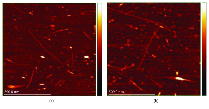
AFM images reported by Hayashida and Umemura. (a) Hybrids of ssDNA and SWNTs. (b) Hybrids of dsDNA and SWNTs. Observation was carried out in a buffer solution (reprinted from Hayashida and Umemura [69] with permission).
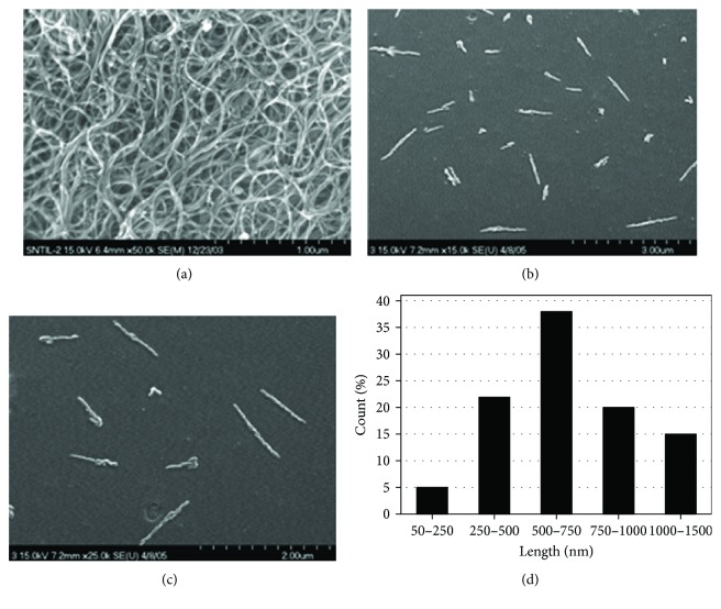
SEM images reported by Nepal et al. (a) An SEM image of SWNTs. (b and c) An SEM image of DNA-SWNTs. (d) Length distribution of DNA-SWNTs (reprinted from Nepal et al. [70] with permission).
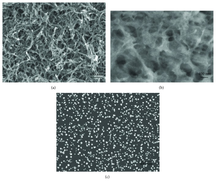
SEM images reported by Wang et al. (a) MWNTs/GCE. (b) PAbA/MWNTs/GCE. (c) Au nanoparticles/PABA/MWNTs/GCE (reprinted from Wang et al. [97] with permission).
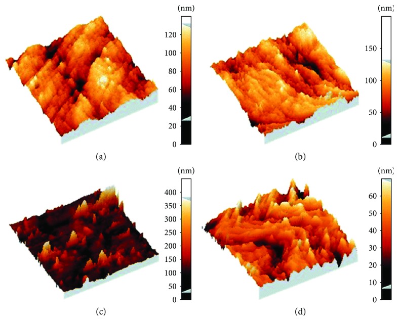
AFM images of functionalized GCE surfaces for DNA mismatch detection. (a) Oxidized bare GCE. (b and d) DNA/oxidized GCE. (c) MWNTs/DNA/oxidized GCE. Scan sizes: 5 × 5 μm in (a), (b), and (c). 1 × 1 μm in (d) (reprinted from Shahrokhian et al. [96] with permission).
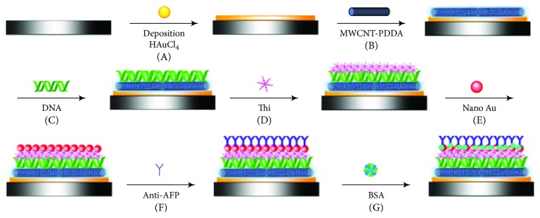
Schematic view of the fabrication process of an immunosensor reported by Ran et al. (A) Deposition of Au nanoparticles. (B) Coating of MWNTs-PDDA layer. (C) Immobilization of DNA film. (D) Formation of thionine layer. (E) Assembly of gold nanoparticles. (F) Anti-AFP loading. (G) BSA blocking (reprinted from Ran et al. [127] with permission).
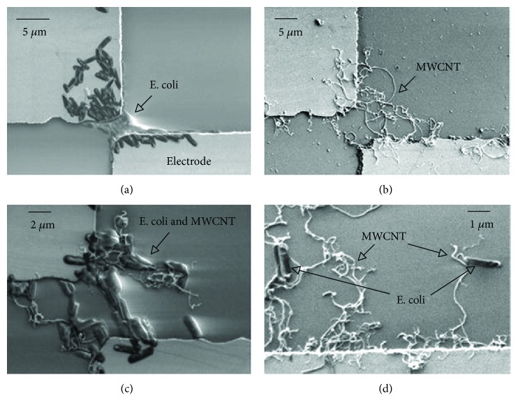
SEM images of trapped E. coli cells and MWNTs between two microelectrodes by DEP force. (a) Trapped cells. (b) Trapped MWNTs. (c) Trapped cells and MWNTs. (d) Cells trapped at the tip of MWNTs (reprinted from Suehiro et al. [157] with permission).
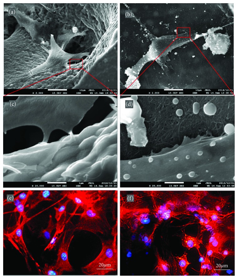
SEM and fluorescence microscope images of MC3T3-E1 cells on IP-CHA and CNTp scaffolds. (a, c, and e) On IP-CHA. (b, d, and f) On CNTp. (a, b, c, and d) IP-CHA and (b and d) CNTp. Magnification: 2000x for (a and c), 20,000x for (c and d). (e and f) Cells were labeled for actin filaments (red) and nucleus (blue) (reprinted from Tanaka et al. [159] with permission).
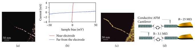
Representative conductive AFM image of a MTJ formed using PPD as the molecular linker and interfaced to a macroscopic metal electrode. (b) Representative I–V curves recorded at selected points across the MTJ: red line for measurements in close proximity to the macroscopic electrode and blue line for measurements at the far end from the macroscopic electrode. (c) Phase AFM image of the MTJ shown in (a). (d) Schematic representation of the conductive AFM measurements on the MTJs (reprinted from Zhu et al. [237] with permission).
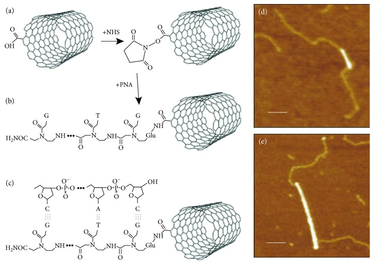
Hybridization of PNA attached SWNTs and DNA. (a and b) PNA was attached to an end of SWNT with N-hydroxysuccinimide (NHS) esters. (c) Hybridization of DNA with PNA attached SWNT. (d and e) AFM images of PNA-SWNTs. Bright lines indicate SWNTs. The paler strands represent bound DNA. Scale bars are 100 nm. Diameters of SWNTs were 0.9 nm and 1.6 nm in (d) and (e), respectively (reprinted from Williams et al. [263] with permission).
Similar articles
-
Probe Microscopic Studies of DNA Molecules on Carbon Nanotubes.Nanomaterials (Basel). 2016 Oct 8;6(10):180. doi: 10.3390/nano6100180. Nanomaterials (Basel). 2016. PMID: 28335308 Free PMC article. Review.
-
Carbon Nanotube Emissions from Arc Discharge Production: Classification of Particle Types with Electron Microscopy and Comparison with Direct Reading Techniques.Ann Occup Hyg. 2016 May;60(4):493-512. doi: 10.1093/annhyg/mev094. Epub 2016 Jan 8. Ann Occup Hyg. 2016. PMID: 26748380 Free PMC article.
-
Real-Time Emission and Exposure Measurements of Multi-walled Carbon Nanotubes during Production, Power Sawing, and Testing of Epoxy-Based Nanocomposites.Ann Work Expo Health. 2022 Aug 7;66(7):878-894. doi: 10.1093/annweh/wxac015. Ann Work Expo Health. 2022. PMID: 35297480 Free PMC article.
-
Binding and condensation of plasmid DNA onto functionalized carbon nanotubes: toward the construction of nanotube-based gene delivery vectors.J Am Chem Soc. 2005 Mar 30;127(12):4388-96. doi: 10.1021/ja0441561. J Am Chem Soc. 2005. PMID: 15783221
-
Carbon nanotubes for delivery of small molecule drugs.Adv Drug Deliv Rev. 2013 Dec;65(15):1964-2015. doi: 10.1016/j.addr.2013.08.005. Epub 2013 Aug 14. Adv Drug Deliv Rev. 2013. PMID: 23954402 Review.
Cited by
-
Dispersion of Carbon Nanotubes with "Green" Detergents.Molecules. 2021 May 14;26(10):2908. doi: 10.3390/molecules26102908. Molecules. 2021. PMID: 34068851 Free PMC article.
-
Stable Near-Infrared Photoluminescence of Single-Walled Carbon Nanotubes Dispersed Using a Coconut-Based Natural Detergent.ACS Omega. 2021 Nov 2;6(45):30708-30715. doi: 10.1021/acsomega.1c04615. eCollection 2021 Nov 16. ACS Omega. 2021. PMID: 34805698 Free PMC article.
References
-
- Ebbesen T. W. Carbon nanotubes. Annual Review of Materials Science. 1994;24(1):235–264. doi: 10.1146/annurev.ms.24.080194.001315. - DOI
Publication types
LinkOut - more resources
Full Text Sources
Other Literature Sources