. 2018 Jul 24;8(1):11116.
doi: 10.1038/s41598-018-29485-5.

Spontaneous formation of fluid escape pipes from subsurface reservoirs

Affiliations

Spontaneous formation of fluid escape pipes from subsurface reservoirs

Ludovic Räss et al. Sci Rep. .

Abstract

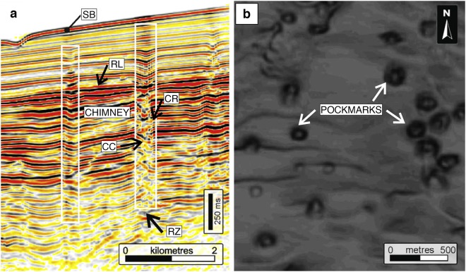
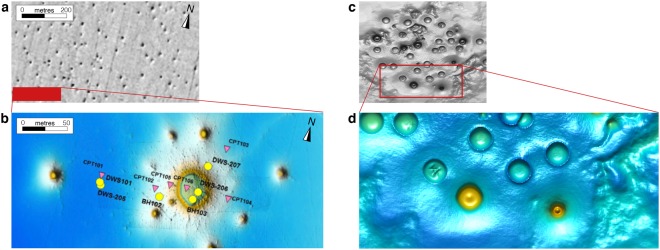
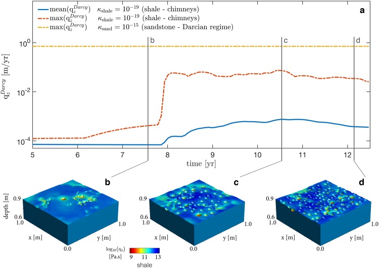
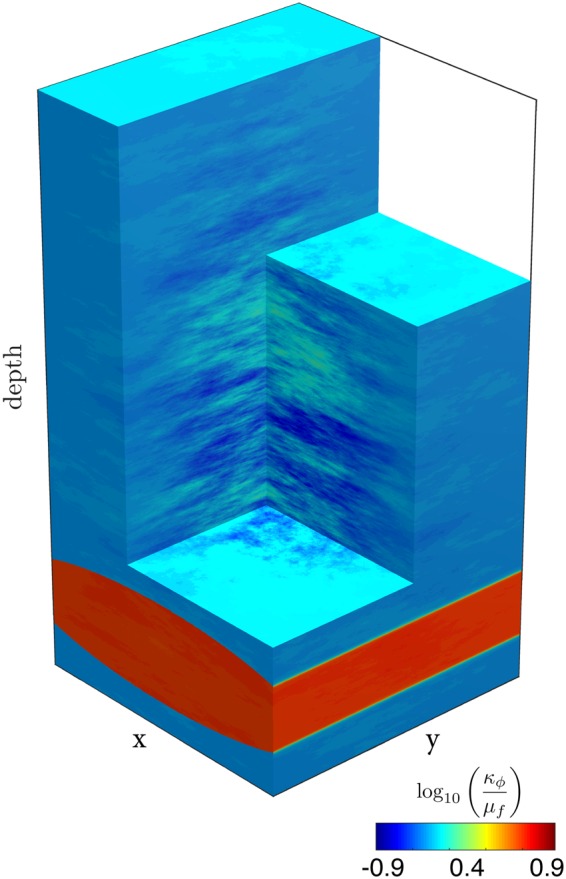
Ubiquitous observations of channelised fluid flow in the form of pipes or chimney-like features in sedimentary sequences provide strong evidence for significant transient permeability-generation in the subsurface. Understanding the mechanisms and dynamics for spontaneous flow localisation into fluid conductive chimneys is vital for natural fluid migration and anthropogenic fluid and gas operations, and in waste sequestration. Yet no model exists that can predict how, when, or where these conduits form. Here we propose a physical mechanism and show that pipes and chimneys can form spontaneously through hydro-mechanical coupling between fluid flow and solid deformation. By resolving both fluid flow and shear deformation of the matrix in three dimensions, we predict fluid flux and matrix stress distribution over time. The pipes constitute efficient fluid pathways with permeability enhancement exceeding three orders of magnitude. We find that in essentially impermeable shale (10-19 m2), vertical fluid migration rates in the high-permeability pipes or chimneys approach rates expected in permeable sandstones (10-15 m2). This previously unidentified fluid focusing mechanism bridges the gap between observations and established conceptual models for overcoming and destroying assumed impermeable barriers. This mechanism therefore has a profound impact on assessing the evolution of leakage pathways in natural gas emissions, for reliable risk assessment for long-term subsurface waste storage, or CO2 sequestration.


Conflict of interest statement

The authors declare no competing interests.

Figures

Figure 1
Figure 1
Seismic expression of chimneys and pockmarks. Figure modified from Cartwright and colleagues,. (a) Vertical seismic profile through fluid migration pathways from offshore Namibia. SB = seabed, RL = reflective horizontal sedimentary layer, CR = chimney downward-bending compacted rim, CC = chimney core, RZ = root zone and diffuse base of the chimney. (b) Horizontal slice through a group of chimneys displaying the typical circular craters or pockmarks.
Figure 2
Figure 2
Comparison of the numerical results to pockmarks observed on the seafloor. (a) Natural data showing pockmarks on the seafloor in part of the Troll field area, offshore Norway. Figure modified from Mazzini and colleagues. (b) Multibeam line across the red rectangular region from (a), displaying high-resolution seafloor mapping of pockmarks. (c) Numerical result from the simulation described in the main text (Fig. 5b,d), reoriented to fit the natural data aspect ratios. (d) Magnification of a specific region of the numerical model results (red rectangle) showing crater distribution, size variation and topography.
Figure 3
Figure 3
High-permeability chimney genesis out of a source region (reservoir) in three dimensions. Colour plot (logarithmic scale) of dynamic permeability (κφ/μf) for two different lithologies, conductive sandstone and impermeable shale. Contoured values show a 1.5 order of magnitude increase in (κφ/μf) representative for the chimneys. (a) Insight into the hydro-mechanical model unveiling the existence of high-permeability chimneys as tubular shaped features in three dimensions. (b) Enlargement of the centre of the model, selectively displaying the contoured chimneys. (c) Vertical two-dimensional slice of (b) displaying a colour plot of the permeability field of an isolated chimney. (d) Horizontal slice of (b) displaying a colour plot of the permeability field, resulting in rounded craters or pockmarks. Effective permeability, time and length scale are given for both permeable sandstones and low-permeability shales.
Figure 4
Figure 4
Chimney formation mechanism. Three successive time laps of two-dimensional vertical (ad) and horizontal (e,f) slices from Fig. 1b. (a,e) Dynamic permeability (logarithmic scale) field. The white arrows represent the fluid flux vectors, scaled by the maximal flux over time and directed into the chimney in the local drainage area, showing flux from outside to inside the chimneys. (b,f) Strain rate-dependent non-linear bulk viscosity values (logarithmic scale). (c,g) Effective pressure (p¯pf) distribution. (d,h) Shear stress deformation magnitude (second invariant of the deviatoric stress tensor). Results are scaled for low-permeable shale (κshale=1019 m2) and permeable sandstone (κsand=1014m2) and display downward-bending compacted chimney rims, permeable chimney cores and circular pockmarks; the characteristic chimney attributes observed in nature. White contour lines (bd,fh) represent the chimney extend, characterised by a significant increase (1.5 order of magnitude) in dynamic permeability.
Figure 5
Figure 5
Fluid flux through a horizontal slice of 1 m2 of low-permeable shale (κshale=1019 m2) located at 1 m above the source region showing corresponding typical circular craters or pockmarks. (a) Mean fluid flux (mean(qzDarcy)) and maximal fluid flux (max(qzDarcy)) values in m/yr through the contributing area (1 m2) as a function of time for chimney populated shale. Comparison with fluid flux through 1 m2 of four orders of magnitude more permeable sandstone (κsand=1015 m2) in pure diffusive Darcian regime without chimneys. Mean and maximal fluid flux values are identical for homogenous permeability distribution in sandstone. (b,d) Expression of craters resulting from flow focusing in high-permeability chimneys. Surface and colour plot of bulk viscosity (ηφ) reflecting the geological records of contrasting material parameters, by analogy to Fig. 1b. (b) First chimney break through after 8 years. (c) Vertical flow peak after 10.5 years. (d) Lowered flux and dormant chimneys after 12 years.
Figure 6
Figure 6
Initial conditions for the numerical simulation. Permeability distribution is set as an anisotropic Gaussian random field throughout the model. A cylindrical ellipse of close to one order of magnitude higher dynamic permeability values (logarithmic scale) compared to the background dimensionless value of 1 is located at ¼ from the bottom of the domain. Gravity is acting downwards and the pore fluid is twice as buoyant as the solid matrix.

References

    1. Connolly JAD, Podladchikov YY. Decompaction weakening and channeling instability in ductile porous media: Implications for asthenospheric melt segregation. J. Geophys. Res. 2007;112:B10205. doi: 10.1029/2005JB004213. - DOI
    1. Ingebritsen, S. E. & Manning, C. E. Permeability of the Continental Crust: Dynamic Variations Inferred from Seismicity and Metamorphism. Front. Geofluids 193–205, 10.1002/9781444394900.ch13 (2011).
    1. Plümper O, John T, Podladchikov YY, Vrijmoed JC, Scambelluri M. Fluid escape from subduction zones controlled by channel-forming reactive porosity. Nat. Geosci. 2017;10:150–156. doi: 10.1038/ngeo2865. - DOI
    1. Sumita I, Yoshida S, Kumazawa M, Hamano Y. A model for sedimentary compaction of a viscous medium and its application to inner-core growth. Geophys. J. Int. 1996;124:502–524. doi: 10.1111/j.1365-246X.1996.tb07034.x. - DOI
    1. Tian M, et al. The Potential for Metamorphic Thermal Pulses to Develop During Compaction-Driven Fluid Flow. Geochemistry, Geophys. Geosystems. 2018

Publication types

LinkOut - more resources