. 2018 Sep;12(9):1986-1999.
doi: 10.1002/term.2733. Epub 2018 Aug 24.

Form and functional repair of long bone using 3D-printed bioactive scaffolds

Affiliations

Form and functional repair of long bone using 3D-printed bioactive scaffolds

Nick Tovar et al. J Tissue Eng Regen Med. 2018 Sep.

Abstract

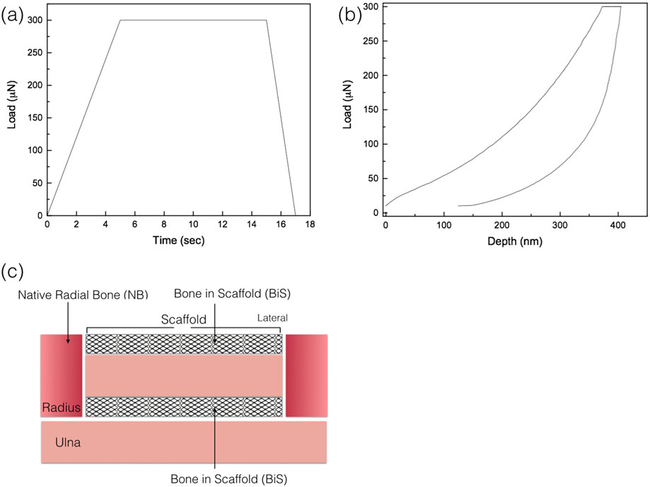
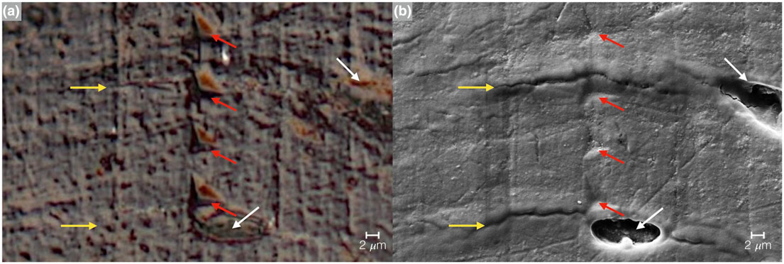
Injuries to the extremities often require resection of necrotic hard tissue. For large-bone defects, autogenous bone grafting is ideal but, similar to all grafting procedures, is subject to limitations. Synthetic biomaterial-driven engineered healing offers an alternative approach. This work focuses on three-dimensional (3D) printing technology of solid-free form fabrication, more specifically robocasting/direct write. The research hypothesizes that a bioactive calcium-phosphate scaffold may successfully regenerate extensive bony defects in vivo and that newly regenerated bone will demonstrate mechanical properties similar to native bone as healing time elapses. Robocasting technology was used in designing and printing customizable scaffolds, composed of 100% beta tri-calcium phosphate (β-TCP), which were used to repair critical sized long-bone defects. Following full thickness segmental defects (~11 mm × full thickness) in the radial diaphysis in New Zealand white rabbits, a custom 3D-printed, 100% β-TCP, scaffold was implanted or left empty (negative control) and allowed to heal over 8, 12, and 24 weeks. Scaffolds and bone, en bloc, were subjected to micro-CT and histological analysis for quantification of bone, scaffold and soft tissue expressed as a function of volume percentage. Additionally, biomechanical testing at two different regions, (a) bone in the scaffold and (b) in native radial bone (control), was conducted to assess the newly regenerated bone for reduced elastic modulus (Er ) and hardness (H) using nanoindentation. Histological analysis showed no signs of any adverse immune response while revealing progressive remodelling of bone within the scaffold along with gradual decrease in 3D-scaffold volume over time. Micro-CT images indicated directional bone ingrowth, with an increase in bone formation over time. Reduced elastic modulus (Er ) data for the newly regenerated bone presented statistically homogenous values analogous to native bone at the three time points, whereas hardness (H) values were equivalent to the native radial bone only at 24 weeks. The negative control samples showed limited healing at 8 weeks. Custom engineered β-TCP scaffolds are biocompatible, resorbable, and can directionally regenerate and remodel bone in a segmental long-bone defect in a rabbit model. Custom designs and fabrication of β-TCP scaffolds for use in other bone defect models warrant further investigation.

Keywords: 3D printing; bioactive ceramic; calcium phosphate; in vivo; regeneration; scaffolds.


Conflict of interest statement

CONFLICTS OF INTEREST

The authors have declared that there is no conflict of interest.

Figures

FIGURE 1
FIGURE 1
Schematic of robocasting machine (3D Inks LLC, Tulsa, OK) used to assemble scaffolds. (a) Overall set-up of machine and (b) magnified set-up of extrusion nozzles (×3) capable of co-depositing multiple materials
FIGURE 2
FIGURE 2
(a) Schematic of extrusion nozzle depositing filaments of material on a layer-by-layer basis and (b and c) Robocad 4.3 rendition of the designed long-bone scaffold, image shows front and side, respectively, respective measurements and indicates the fugitive support structure (Doutside = 4.85 mm, Dinside = 2.35, and length = 10.5 mm). Also, the intermittent computer-aided design layers of the structure are shown to better illustrate the build process, (d) Layer 0, (e) Layer 8, and (f) Layer 21. β-TCP: beta tricalcium phosphate
FIGURE 3
FIGURE 3
(a) Load as function of time, quasistatic testing profile; (b) a representative load displacement graph of the nanoindentation analysis; and (c) schematic representation of areas where nanoindentation was performed: native radial bone (NB) and bone in scaffold (BiS)
FIGURE 4
FIGURE 4
Scanning electron microscope (SEM) micrographs of the 100% β-TCP, (a) green state and (b) sintered to 1,100°C for 4 hr. The images were taken field emission SEM (Hitachi S-4800, Santa Clara, CA) at 15 kV
FIGURE 5
FIGURE 5
X-ray diffraction spectra for (a) the raw beta tricalcium phosphate (β-TCP) as received from the supplier and (b) represents the sintered to 1,100°C scaffold, with a few of the most intense diffraction peaks representative of β-TCP indicated with an (*). (c) Fourier-transform infrared spectroscopy spectra is shown for the sintered scaffold with few representative groups denoted with respective symbols
FIGURE 6
FIGURE 6
The figure represents the spectra from the (a) differential scanning calorimetry and (b) thermogravimetric analysis of the 100% beta tricalcium phosphate scaffold being subjected to a heating profile similar to that of the sintering profile
FIGURE 7
FIGURE 7
Three-dimensional Amira rendering of the negative control at 8 weeks. (a) Top view of the radius defect with visible bone plate screw holes (white arrows). The bone plate and screws were removed for viewing purposes; (b) lateral view of radial defect with the ulna visibly present (red arrow); (c) μCT cross-sectional slice representing a two-dimensional representation of the radius, radius defect, and ulna visible; and (d) representative histological cross section of the negative defect in the radius, with the white arrows indicating the screw locations for the surgical hardware
FIGURE 8
FIGURE 8
Three-dimensional Amira rendered representation of the radius samples with 3D-printed bioactive ceramic (3DPBC) scaffold (purple) and bone (green) at (a) 8 weeks, (b) 12 weeks, and (c) 24 weeks. Histological cross section of the radius defect along the long axis of the 3DPBC scaffold and defect site at (d) 8 weeks, (e) 12 weeks, and (f) 24 weeks. The marrow (M) space is visible with yellow marrow observed at 12- and 24-week time points. Stevenel’s blue and Van Gieson Picro Fuchsin stained
FIGURE 9
FIGURE 9
Bone, scaffold, and soft tissue/empty space percentage analysis following μCT scanning and Amira software volumetric quantification. Mean and 95% confidence interval values for bone and scaffold percentage quantification. Letter case denote statistically homogenous groups for respective group (capital, scaffold; lower case, bone)
FIGURE 10
FIGURE 10
Histological cross section of the radius defect along the long axis of the three-dimensional-printed bioactive ceramic scaffold and defect site at 8 weeks: (a) low magnification and (b) high magnification. White arrows denote signs of primary osteon formation, and yellow arrows denote woven bone. At 12 weeks: (c) low magnification and (d) high magnification. White arrows denote signs of further osteon formation, and yellow arrows denote woven bone. At 24 weeks: (e) low magnification and (f) high magnification. Green arrows denote Haversian canals, white arrows denote signs of further osteon formation, and yellow arrows denote woven bone. Stevenel’s blue and Van Gieson Picro Fuchsin stained
FIGURE 11
FIGURE 11
Imaging of the nanoindentation testing marks via (a) optical microscope image and (b) SEM micrograph. The red arrows indicate the indentation points, yellow arrows represent lamellae, and white arrows osteocyte lacunae
FIGURE 12
FIGURE 12
Nanoindentation values of hydrated bone samples at 8, 12, and 24 weeks with native radius for comparison: (a) reduced elastic modulus (ER) of the three time points resulted in statistically homogenous to that of the native radial bone (p = 0.11); (b) hardness (H) of bone at 8 and 12 weeks had similar means, whereas the values at 24 weeks were statistically greater than the two previous time points and achieved statistical homogeneity values relative to native bone

References

    1. Baldassarri M, Bonfante E, Suzuki M, et al. (2012). Mechanical properties of human bone surrounding plateau root form implants retrieved after 0.3–24 years of function. Journal of Biomedical Materials Research Part B: Applied Biomaterials, 100(7), 2015–2021. - PubMed
    1. Bose S, Tarafder S, & Bandyopadhyay A (2016). Effect of chemistry on osteogenesis and angiogenesis towards bone tissue engineering using 3D printed scaffolds. Annals of Biomedical Engineering, 1–12. - PMC - PubMed
    1. Bose S, Vahabzadeh S, & Bandyopadhyay A (2013). Bone tissue engineering using 3D printing. Materials Today, 16(12), 496–504.
    1. Chao EY, Aro HT, Lewallen DG, et al. (1989). The effect of rigidity on fracture healing in external fixation. Clinical Orthopaedics and Related Research, 241, 24–35. - PubMed
    1. Coelho PG, Coimbra ME, Ribeiro C, Fancio E, Higa O, Suzuki M, & Marincola M (2009). Physico/chemical characterization and preliminary human histology assessment of a β-TCP particulate material for bone augmentation. Materials Science and Engineering: C, 29(7), 2085–2091.

Publication types

Substances

LinkOut - more resources