Review
. 2019 Jan;92(1093):20180226.
doi: 10.1259/bjr.20180226. Epub 2018 Aug 13.

CT angiography for depiction of complications after the Bentall procedure

Affiliations
Review

CT angiography for depiction of complications after the Bentall procedure

Sara Boccalini et al. Br J Radiol. 2019 Jan.

Abstract

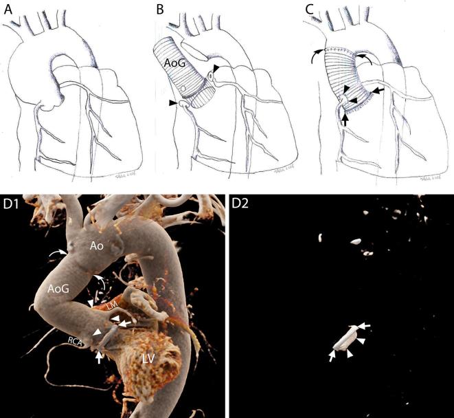
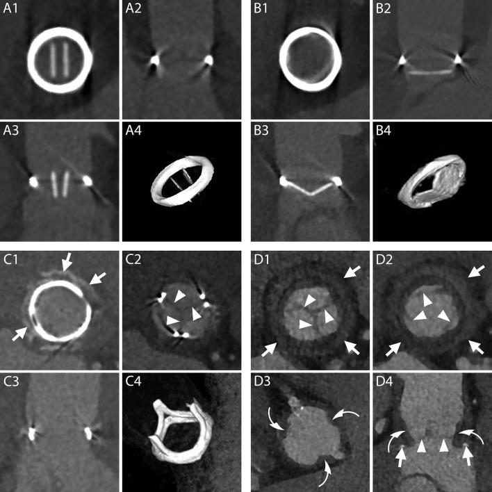
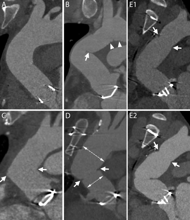
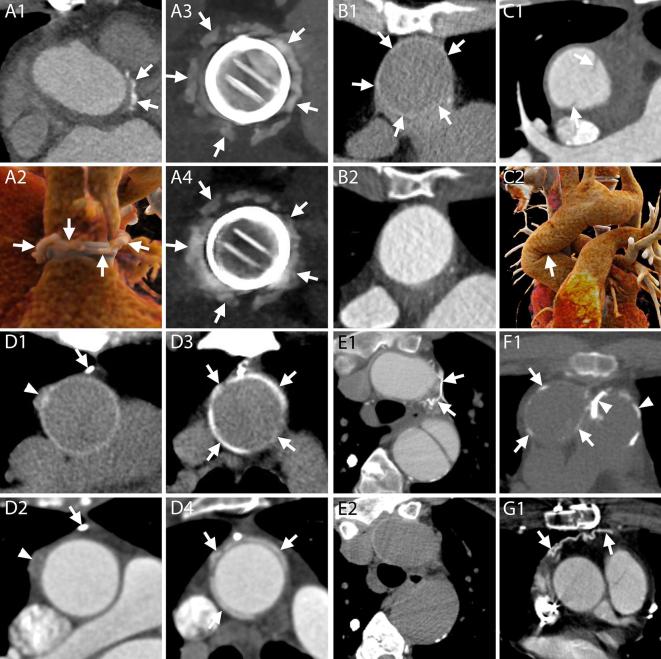
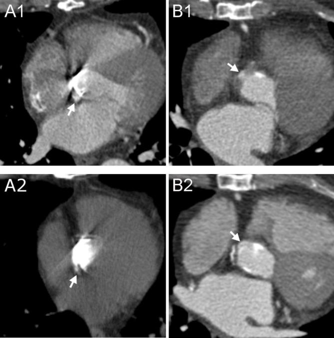
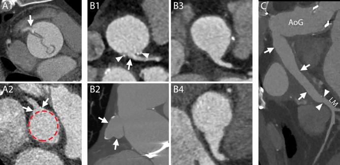
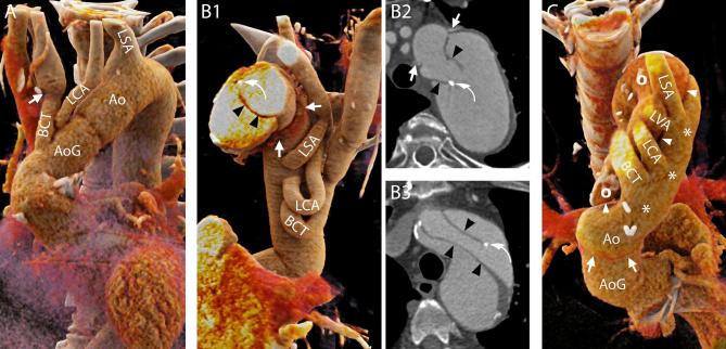
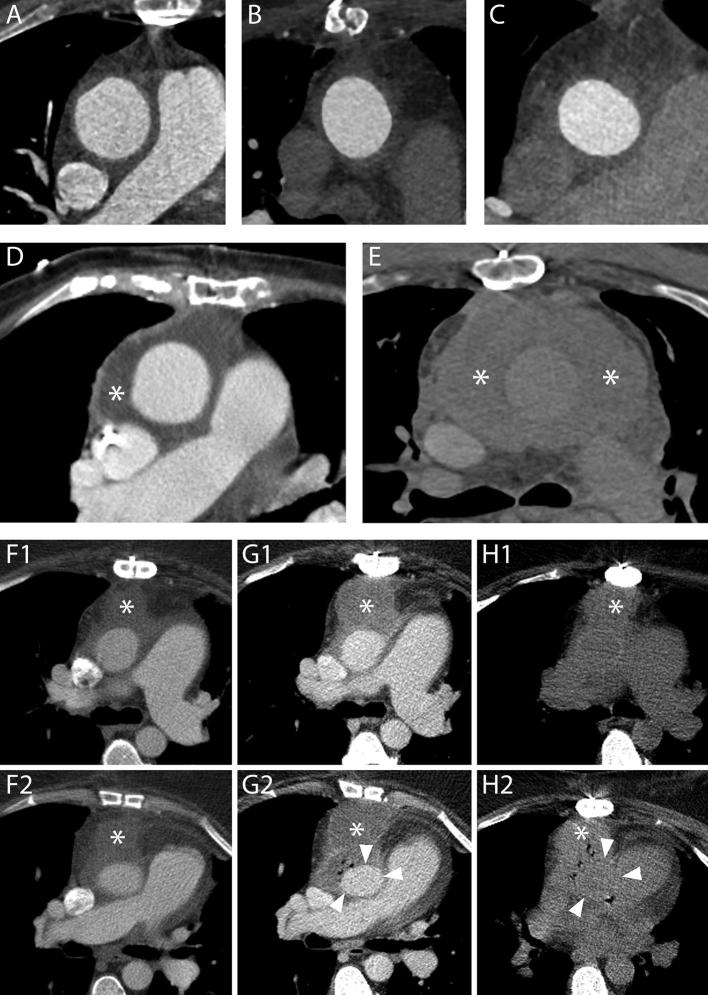
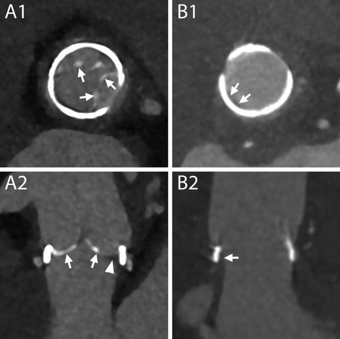
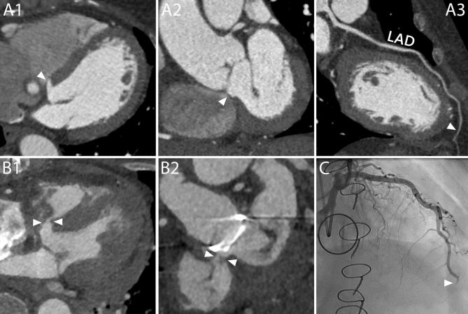
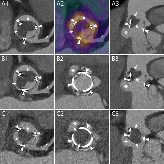
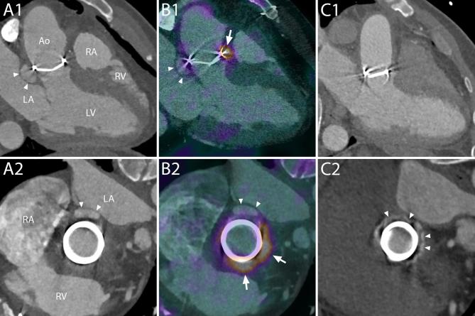
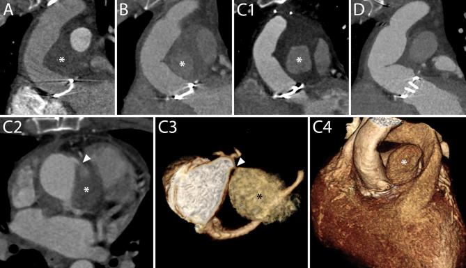
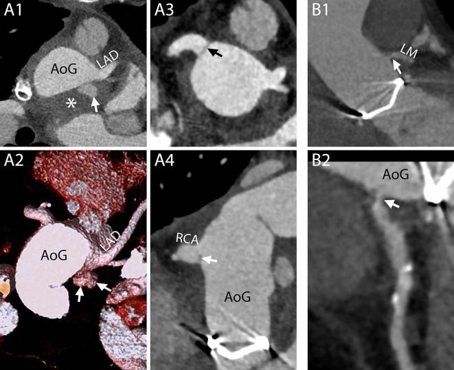
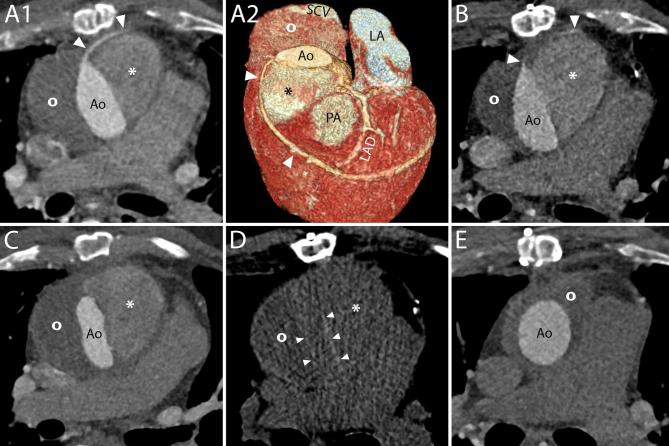
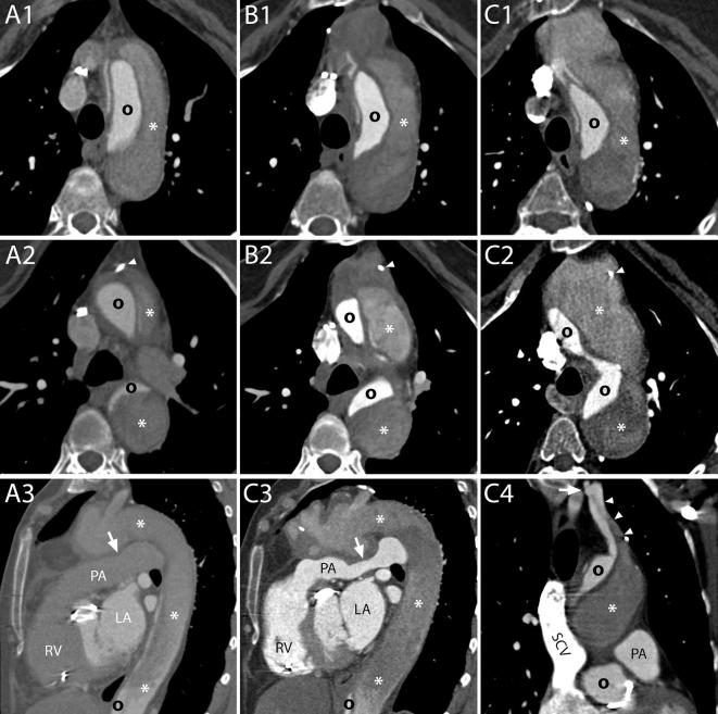
Following a Bentall procedure, which comprises a composite replacement of both the aortic valve and the ascending aorta, the imaging modality of choice to depict known or suspected complications is CT angiography. An update and extension of the literature regarding complications after the Bentall procedure is provided. The wider availability of ECG-gating has allowed for a clearer depiction of the aortic valve and ascending aorta. This resulted not only in the identification of previously undetectable complications, but also in a more precise assessment of the pathophysiology and morphology of known ones, reducing the need for additional imaging modalities. Moreover, the possibility to combine positron emission tomography images with CT angiography offers new insights in case of suspected infection. Due to the complexity of the operation itself and concomitant or subsequent additional procedures, as well as the wide spectrum of underlying pathology, new scenarios with multiple complications can be expected.


Figures

Figure 1.
Figure 1.
The Bentall procedure. A–C, Schematic representations of the most commonly practiced variation of the Bentall procedure. The native wall of the aneurysmatic (A) or dissected ascending aorta is excised together with the stenotic or insufficient aortic valve (interposition technique). The ostia of the coronary arteries are cut out with a button of the native aortic wall attached (button technique) (B, arrow heads). The aorta and the aortic valve are substituted by one or multiple grafts (B, AoG) and a prosthetic aortic valve which are sutured to the LVOT (C, arrows) and the native aorta (C, curved arrows). The buttons around the coronary ostia are reattached to the aortic graft (C, arrow heads). D1–D2, 3D reconstructions of CTA images of a patient who underwent a Bentall procedure with the implantation of a mechanical aortic valve, performed according to the technique described above, showing the exterior surface of the aortic prosthesis and native aorta (D1) and the prosthetic aortic valve within (D2), respectively. D1, Ring of the aortic valve (arrows); AoG; anastomosis of the coronary arteries (arrow heads); distal suture line with the native aorta (curved arrows). D2, Metallic ring of the aortic valve (arrows); leaflet of the mechanical valve (arrow heads). Ao, native aorta; AoG, aortic grafts; LM, left main; LV, left ventricle; LVOT, left ventricleoutflow tract; RCA, rightcoronary artery.
Figure 2.
Figure 2.
Normal aspect of prosthetic aortic valves. A1–B4, CT aspect of the most commonly employed mechanical prosthetic valve (St. Jude, Abbott, Illinois, USA). The bi-leaflet valve is shown with open and closed leaflets respectively during systole (A1–A4) and diastole (B1–B4). A1, B1, MPR on planes perpendicular to the center line of the aorta at the level of the outer ring of the valve. A2, B2, MPR parallel to the centerline of the aorta and parallel to the direction of the leaflets. A3, B3, MPR parallel to the centerline of the aorta and perpendicular to the direction of the leaflets. A4, B4, VR of the valve. C1–C4, CT aspect of a stented biological valve during diastole. C1, C2, MPR on planes perpendicular to the centerline of the aorta respectively at the level of the most caudal (C1) and most cranial (C2) part of the metallic stent. In C1 the pledgets used to reinforce the sutures on the suture ring are visible (arrows). The biological leaflets are attached to the frame and when closed have an appearance similar to a native tricuspid aortic valve (C2, arrow heads). C3, MPR parallel to the centerline of the aorta. C4, VR of the valve. D1–D4, CT aspect of a stentless biological valve. D1, D2, MPR on planes perpendicular to the centerline of the aorta at the level of the suture ring of the valve (arrows) showing the three closed (D1) and open (D2) leaflets (arrow heads). D3, More cranially, at the level of the coronary arteries ostia, the outer frame of the valve appears as small hypodense irregularities (curved arrows) of the aortic contour protruding in the lumen. D4, An MPR parallel to the center line of the aorta shows the cusps of the leaflets (arrow heads), the outer frame of the valve (curved arrows) and the pledgets used to reinforce the sutures (arrows). MPR, multiplanar reconstructions; VR, volume rendering.
Figure 3.
Figure 3.
Normal aspect of aortic grafts. A, The aortic graft can present a smooth outer contour and appear similar to a native aorta. B, Especially in case of a sharp angulation of the ascending aorta and in case a long graft has been employed, the fabric of the graft can present an inward fold projecting inside the aortic lumen (arrow). The small grooves of the outer surface of the graft can also be visible on CT scans (arrow heads). C, When two grafts are employed, a sharp angle in the contour of the ascending aorta may develop at the level of the connection (arrows). D, If needed for anatomical reasons, the two employed grafts can have different sizes (two dashed lines) and a slight inward fold is seen at the level of the suture (arrows). E1–E2, – Two consecutive scans of the same patient, acquired within less than 1 year, show a change in angulation and appearance of the aortic grafts. The distal suture of the more caudal of the grafts with the native aorta is evident as it appears as a stricture in the aortic contour (E1–E2, arrows).
Figure 4.
Figure 4.
Surgical material and potential pitfalls. A1–A4, CT appearance of pledgets. After a Bentall procedure or surgical aortic valve replacement, hyperdense material can be seen around the aortic root on axial images (A1, arrows). These hyperdense images represent pledgets that are employed by surgeons to reinforce the sutures on the suture ring of the valve and should not be mistaken for extravasated contrast. The material can be seen surrounding the junction of the LVOT and the aortic root (A2, arrows), at a short distance from the valvular ring (A3, arrows), although generally not all on the same plane (A2). An unenhanced acquisition can be useful to assess the presence of the images also before contrast administration and confirm their nature (A4, arrows). A1, Axial image. A2, 3D reconstruction. A3–A4, MPR with maximum intensity projection reconstructions on planes perpendicular to the centerline of the aorta of enhanced and unenhanced acquisitions, respectively. B1–B2, CT appearance of the aortic graft. B1, On unenhanced acquisitions, the aortic graft appears as a thin rim of hyperdense material (arrows). B2, On contrast-enhanced acquisitions, the graft cannot be distinguished from the contrast in the aortic lumen. B1–B2, Axial images. C1–C2, At the level of the ascending aorta, one or two hypodense lines can be spotted in the aortic lumen (C1, arrows) of some post-Bentall scans. They should not be mistaken for new or residual intimal flaps as they represent an inward fold of the graft that can be more easily identified on VR (C2, arrow) or MPR reconstructions (see panel B of Figure 3). C1, Axial image. C2, 3D reconstruction. D1–D4, Surgical material adjacent to the aortic graft. D1–D2, Surgical material includes metallic clips with very high attenuation values (D1, D2, arrows) as well as other slightly hyperdense structures (D1, D2, arrowheads), usually placed at the cannulation sites, which are identifiable on unenhanced acquisitions (D1) but can hardly be distinguished from the adjacent periaortic tissue on enhanced acquisitions (D2). D3–D4, PTFE can be employed to reinforce the distal suture line of the aortic graft and appears as hyperdense material surrounding the aorta (D3, D4, arrows), on both unenhanced (D3) and enhanced acquisitions (D4). D1–D4, MPR. E1–E2, It is not uncommon in these patients to have collateral vessels in the mediastinum that might fill with contrast (E1, arrows) and may therefore appear very hyperdense, making them easy to be mistaken for surgical material. Contrary to surgical material, the vessels are not visible on corresponding unenhanced slices (E2). E1–E2, F1, G1, Axial images. F1, Calcifications can appear on aortic grafts (arrows) implanted years before (in this case example, the Bentall had been performed 12 years prior to the CT scan). Calcifications may also be seen at the level of the pulmonary valve (arrow heads) indicating a previous Ross procedure. G1, After the procedure the pericardium is generally left open and without sutures. However, in some circumstances, it can be closed with a patch of synthetic material (arrows). LVOT, left ventricle outflow tract; MPR, multiplanar reconstructions.
Figure 5.
Figure 5.
Differentiation between surgical and contrast material. A1–A2, Surgical material adjacent to the prosthetic valve possibly mistaken for contrast medium. On enhanced acquisitions (A1), a hyperdense rounded structure situated in the close proximity of proximal (or distal) suture lines (arrow) could be interpreted as surgical material, particularly a pledget, or as extravasated contrast medium. However, on unenhanced acquisitions (A2) only surgical material is visible (arrow) and, therefore, hyperdense structures present in the same location on both acquisitions are attributed to exogenous matter employed during the Bentall procedure. B1–B2, Small pseudoaneurysm mistaken for surgical material. On a first postoperative scan (B1) an axial image of an enhanced acquisition showed a small hyperdense structure (arrow) close to the aortic prosthesis that was not reported as it was mistaken for a pledget. In this case an unenhanced acquisition was not performed. The real etiology of this structure was appreciated on a second enhanced exam (B2) where, due to changes in aortic orientation, it was clear that the structure (arrow) was in communication with the LVOT and should therefore be referred to a small pseudoaneurysm. LVOT, left ventricle outflow tract.
Figure 6.
Figure 6.
Normal aspect of coronary artery sutures and origin. A1–A2, The most commonly practiced version of the Bentall procedure includes preservation of a “button” of native aortic wall around the coronary ostia that will be sutured to the aortic graft. Therefore, most commonly, even coronaries that before the operation had an abrupt origin from the aortic wall (A1, arrow) after the operation will show an enlarged emergence (A2, arrows) protruding from the circular profile of the graft (A2, dashed line) due to the additional tissue of the button of the native aorta. A1–A2, MPR perpendicular to the centerline of the aorta. B1–B4, B1 and B2, Depending on the extension of the resected native aortic wall, the appearance of the new origin of the coronary artery can be very different, as shown in these two case examples: almost normal (B1, arrow at the origin of the left coronary artery) or very enlarged (B2, arrows at the origin of the right coronary artery). Surgical material can be seen at the level of the suture lines (B1, arrow heads). B3 and B4, The shape of the origin can be different as well, and can have a “trumpet-like” (B3) or “flask-like” (B4) appearance. B1, B3, B4, MPR perpendicular to the centerline of the aorta. B2, MPR parallel to the centerline of the aorta. C, A graft (arrows) can be interposed between the AoG and the native coronary artery (arrow heads). In this case the procedure is referred to as “Cabrol procedure”. CPR. AoG, aortic grafts; CPR, curved planar reformation; LM, left main; MPR, multiplanar reconstructions; VR, volume rendering.
Figure 7.
Figure 7.
Normal aspect of the aortic arch and aortic branches. A, Hemi-arch replacement. In this patient, the aorta was replaced up to the mid-arch. Therefore, only the BCT and the LCA were “debranched” and reattached to the aortic graft with the interposition of surgical grafts. In some cases, the level of the suture line along the aortic branches can be easily recognized due to the mismatch of caliber between the native vessel and the graft (arrow). On the contrary, the LSA was left attached to the native aortic arch. 3D reconstruction. B1–B2 and B3, Elephant trunk (B1–B2) and confounders (B3). In case the entire arch has to be replaced and the descending aorta is dilated to such an extent that further interventions are required, the “Elephant trunk” technique can be employed. During the first step of this procedure, the aortic arch is replaced and sutured to the native aorta, where the felt used to reinforce the suture can be seen on CT images (B1, B2, arrows), and the BCT, LCA and LSA are reattached to the graft (B1). The most characteristic feature of the procedure is that the aortic graft has some additional fabric attached to the distal edge that is left floating freely in the lumen of the native aorta (thus the name “elephant trunk”) and will guide and ease future interventions on the proximal descending aorta. The fabric appears on CT images as hypodense lines (B1–B2, arrowheads) that should not be mistaken for intimal flaps that might have an analogous aspect (B3, arrowheads). Although a metallic component is added to the distal end of the trunk to ease its visualization (B1, B2, curved arrows), intimal flaps can have similar looking calcifications (B3, curved arrows). B1, 3D reconstruction. B2, B3, Axial images. C, Residual dissection. Distal to the suture line (arrows) of the aortic graft the dissection can be left into place with its true lumen (asterisks) in continuity with the lumen of the graft. The aortic branches (including the independent origin of the LVA all originated from the true lumen very close to the intimal flap (arrow heads) and the false lumen (circles). 3D reconstruction seen from above. 3D, three-dimensional; Ao, native aorta; AoG, aortic graft; BCT, brachiocephalic trunk; LCA, left carotid artery; LSA, left subclavianartery; LVA, left vertebral artery
Figure 8.
Figure 8.
Periaortic fluid in the form of stranding and fluid collections. A–C, Three different cases showing increasing amounts of periaortic fluid in the form of stranding. The scans were performed 55 (A), 69 (B) and 59 (C) days after an uncomplicated operation, respectively. In all cases, the patients had undergone an uneventful procedure and did not have any complications within the first year following the operation. D, A fluid collection with water-like content (asterisk) 12 days after a Bentall procedure in an 83-year-old female. The patient was reoperated 9 months later because of progressive dilation of the descending aorta. E, The day after a Bentall operation for type A dissection extending to the right carotid artery, this 61-year-old male presented a reduction of hemoglobin levels that prompted to investigate the source of bleeding. A CT scan was performed which highlighted the presence of a hematoma completely surrounding the aorta (asterisks). The patient died two days later for neurological complications. F1–H2, A 53-year-old female who had undergone a Bentall and a MAZE procedure four days before started complaining of posterior chest pain at the level of Th7. A CT scan (F1, F2) performed for the suspicion of spondilodiscitis or mediastinitis demonstrated a fluid collection (asterisks) with water-like density surrounding the aortic graft. Three days later, the patient had high fever and a new CT scan was performed to locate the focus of infection. Axial images (G1, G2) showed an increase in diameter of the previously reported fluid collection (asterisks) that had, at that time, clear characteristics of an abscess with air bubbles inside and slight compression of the prosthesis (arrow heads). Appropriate antibiotic therapy was started. The day after an unenhanced CT scan (H1, H2) demonstrated an increase in the air content of the collection (asterisks) albeit with an overall reduction in size and a restoration of the normal aortic graft appearance (arrow heads). The following day, the patient was reoperated and the collection drained.
Figure 9.
Figure 9.
Mechanical alterations to aortic valve prosthesis function. A1–A2, MPR reconstructions perpendicular (A1) and parallel (A2) to the centerline of the aorta demonstrating calcifications (arrows) and thickening (arrow heads) of the leaflets of a biological valve implanted 7 years before this scan in a 37-year-old male. The degeneration of the leaflets caused a severe, although asymptomatic, stenosis (4,5 m s-1 at echo) and the valve was replaced a few months later. B1–B2, A follow-up CT scan in an 81-year-old female revealed the presence of a thin rim of hypodense material (arrows) adjacent to the ring of this biological valve, which was implanted 4 months before, on both MPR reconstructions perpendicular (B1) and parallel (B2) to the centerline of the aorta. Although an infectious origin could not be ruled out with certainty based solely on CT characteristics, the laminated and smooth aspect of the material along the contour of the metallic ring indicated that it should more likely be ascribed to thrombus/pannus. MPR, multiplanar reconstructions.
Figure 10.
Figure 10.
Small perforation of the membranous ventricular septum after resuscitation of a patient with a Bentall prosthesis due to an acute mid-LAD occlusion approximately 1 month after implantation. This 70-year-old female patient without prior history of coronary artery disease underwent a Bentall procedure for a dilated ascending aorta. At the last follow-up scan prior to the procedure, a distinct thin membranous part of the septum was clearly illustrated (A1, A2, arrow heads). No signs of any concomitant coronary artery disease were found (A3). 1 month after Bentall implantation, the patient experienced an acute STEMI with ventricular fibrillation, for which she was successfully resuscitated. An emergency CT scan didn’t show any signs of aortic dissection, but did give the impression of a small perforation (arrow heads) of the membranous ventricular septum on the axial images (B1), which became even more evident on the multi planar reconstructions (B2), possibly due to either the Bentall implantation or the resuscitation itself. Coronary angiography revealed a new mid-LAD occlusion (C, arrow head) as the probable cause of the STEMI, but ensuing emergency PCI attempts failed. Although it is possible that a high Doppler signal over such a small perforation may have been overlooked, echocardiography did not show any signs of flow over the septum during follow-up, and the patient was discharged later on with good left ventricular function. LAD, left anterior descending artery; PCI, percutaneous coronary intervention; STEMI, ST elevated myocardial infarction.
Figure 11.
Figure 11.
Endocarditis of a biological valve with a mass obstructing the aortic lumen of uncertain origin and a pseudoaneurysm in the LVOT. 1 year after having undergone a Bentall procedure for endocarditis, this 80-year-old male presented with fever and blood cultures positive for S. aureus and Candida parapsilosis. A CT scan revealed the presence of a big hypodense mass (A1, arrows) attached to the structure of the valve (A1, arrow heads) and partially occluding the aortic lumen. A PET/CT, the images of which were fused with those of the CTA, demonstrated increased uptake of FDG at the level of the structure of the valve (A2, arrow heads) but not of the mass itself (A2, arrows). Therefore, doubts arose regarding the aetiology of the mass and whether it should be considered a vegetation (PET-negative because of incarceration of pathogen agents in the midst of fibrotic tissue and consequent lack of inflammatory response), a thrombus or a combination of the two. However, due to the positive PET exam and to the additional presence of a pseudoaneurysm (A3, asterisk) just below the valve (A3, arrowheads) and the mass (A3, arrows), which confirmed the occurrence of a destructive infectious process, the patient was treated with antibiotics and antifungals. Two weeks later a new CT scan was performed (B1-C3) with ECG-gating and reconstructions in both systole (B1-B3) and diastole (C1-C3). The new exam did not reveal any reduction in the size of the mass (B1, B3, C1-C3, arrows) which was still attached to the structure of the valve (B1, B3, C1-C3, arrowheads) and even appeared slightly bigger. The pseudoaneurysm remained was unchanged in size (B2-B3, C2-C3, asterisks). Assessment of the dynamics of the mass during the cardiac cycle demonstrated partial obstruction of the aortic lumen during systole (B1-B3) with patent valve opening (B2, arrows) that was almost completely occluded during diastole with protrusion of the mass below the level of the metallic ring (C2-C3). The patient died 12 days later because of uncontrolled candidemia. A1-A2, B1, C1, MPR on planes perpendicular to the centerline of the aorta at the level of the left coronary artery. B2-C2, MPR on planes perpendicular to the centerline of the aorta at the level of the metallic ring of the valve. A3-C3, MPR on planes parallel to the centerline of the aorta. CTA, CT angiography; ECG, electrocardiography; FDG, fluorodeoxyglucose; LVOT, left ventricle outflow tract; PET, positron emission tomography.
Figure 12.
Figure 12.
Endocarditis of a mechanical aortic valve prosthesis after Bentall procedure, with an aseptic perivalvular extension on fused 18F-FDG PET-CT angiography. A 47-year-old male patient who had undergone a Bentall-procedure for a dilated ascending aorta nine years before, was initially admitted for palpitations due to a new atrial flutter. Upon further questioning, it appeared he had been experiencing intermittent fevers over the previous weeks. Blood cultures were positive for a Gram-positive Streptococcus, and transesophageal echo revealed a small cavity close to the posterior annulus, which was found to be a peri-valvular extension (i.e. pseudoaneurysm) on subsequent CT angiography (A1, A2, arrow heads). Interestingly, the 18F-FDG PET/CT scan (B1, B2, Supplementary Video 1), which is increasingly being used in patients suspected of prosthetic valve endocarditis and is now a new major diagnostic criterion according to the ESC Guidelines for infective endocarditis, revealed intense uptake of FDG around the entire annulus (after 12 days of intravenous antibiotics) (arrows), except for the posterior part where the pseudoaneurysm was located (Supplementary Video 2). The patient was electively reoperated, the infected surgical material (including the peri-valvular extension) removed, and a new composite valvular and aortic prosthesis was successfully implanted. Swab cultures of the valve and tissue of the pseudoaneurysm showed no growth of any micro-organisms (after 22 days of intravenous antibiotics), and histopathology revealed only a slight chronic inflammation. Follow-up imaging (C1, C2) nicely showed the hyperdense felt pledgets around the new prosthetic valve, without any signs of endocarditis. Ao, aorta; FDG, fluorodeoxyglucose; LA, left atrium; LV, left ventricle; PET, positron emission tomography; RA, right atrium; RV, right ventricle.
Figure 13.
Figure 13.
Gradually changing content of a pseudoaneurysm after Bentall procedure due to contrast leakage from the right coronary anastomosis. A 30-year-old male patient who had undergone a Bentall procedure for acute Type-A aortic dissection three years before, was readmitted to the ER for acute chest pain. During routine yearly follow-up, a collection of fluid had been identified around the aortic root and ascending aorta, which, although its density had increased, had not changed in size (A, B, asterisks). The routine clinical work-up at admission did not show any signs of acute myocardial infarction, but additional CT angiography (C) now showed a significant increase in size of the fluid collection, and clearly demonstrated the presence of contrast material inside (C1, asterisk). A closer evaluation of the axial images (C2) revealed a “puff” of contrast emanating from the anastomosis of the right coronary button (arrow head), and the additional 3D volume rendering reconstructions highlighted this connection (C3, C4, Supplementary Videos 3 and 4). The pseudoaneurysm was successfully removed during reoperation, as shown on a post-operative CT scan (D), whereafter the leakage was macroscopically confirmed to originate from the anastomosis of the right coronary artery and could successfully be sealed. 3D, three-dimensional; ER, emergency room.
Figure 14.
Figure 14.
Complications at the site of coronary arteries anastomosis and ostia. A1-A4, Different complications involving the two coronary arteries in the same patient. On a CT scan performed 1 month after a Bentall procedure, this 27-year-old male showed signs of complications at both coronary arteries. At the level of the suture line of the left main, a small collection of extravasated contrast material (A1 and A2, arrows) surrounded by a hematoma (A1, asterisk) was identified. The right coronary artery, that had to be reattached a second time to the aortic graft due to bleeding from the first suture, presented a hypodense line at the ostium (A3 and A4, arrows) that could be attributed to a small intimal flap or to an inward fold of the graft. No invasive or surgical treatment was undertaken. A1, Axial mage. A2, VR. A3, MPR perpendicular to the centerline of the aorta. A4, MPR parallel to the centerline of the aorta. B1-B2, Stenosis of the coronary ostium. On a routine follow-up CT scan performed 5 months after the procedure, this 60-year-old male showed a stenosis of the left coronary artery (B1 and B2, arrows). B1, MPR parallel to the centerline of the aorta. B2, CPR. AoG, aortic graft; LAD, left anterior descending; LM, left main; RCA, right coronary artery.
Figure 15.
Figure 15.
Loss of vein graft following combined Bentall and coronary artery bypass procedure due to progressive compression by two fluid collections. This 68-year-old male patient underwent a combined Bentall and coronary artery bypass procedure for a severely stenosed bicuspid aortic valve and concomitant three-vessel disease. Like most Bentall procedure performed at our institution, the interposition technique was used, implying that the native ascending aorta was excised and replaced by a vascular prosthesis (as opposed to the inclusion technique by which the aneurysm sac is closed around the vascular graft). Routine follow-up CT 2 months later (A1, A2) showed two fluid collections, one (asterisk) denser than the other (circle), and both moderately compressed the aortic graft and encompassed but did not compress the vein graft (arrow heads). Two follow-up scans were acquired 4 months (B) and 10 months later (C), which did not show any distinguishable change in size of both fluid collections, but did reveal that the aortic prosthesis—and now also the vein graft (arrowheads)—had become compressed even further (B, C), resulting in occlusion of the vein graft (C). An additional non-enhanced scan (D) did not show any differences in density between the two fluid collections compressing the aortic graft (arrow heads), indicating that the denser fluid collection (asterisk) had to have been partially filled with contrast on all previous contrast-enhanced scans. The patient was thereupon electively reoperated, the leaking right coronary artery button was resutured and the pseudoaneurysm successfully removed, restoring normal aortic dimensions (E) and leaving only a small hematoma behind (circle). Ao, aorta; SCV, superior caval vein; LA, left atrium; PA, pulmonary artery; LAD, left anterior descending.
Figure 16.
Figure 16.
Natural history of a growing false lumen of a residual dissection after Bentall procedure for acute Type-A aortic dissection in a patient with Marfan’s syndrome. This 63-year-old female patient with a family history of Marfan’s syndrome underwent a Bentall procedure for acute Type-A aortic dissection at the age of 57 years. The first post-operative follow-up scan depicted a residual dissection of the aortic arch and descending aorta (A) with a large false lumen (asterisk) and a compressed true lumen (circle). Over the ensuing 5 years, follow-up imaging showed a gradual enlargement of the persisting, partially thrombosed aneurysm sac directly distal to the aortic prosthesis, shown here at the level of the distal suture (A1C1) and approximately 15 mm below (A2C2, Supplementary Video 5), at the level of a metallic surgical clip (arrow heads), clearly illustrating the anterolateral expansion of the outer aortic wall. After 5 years, the aneurysm sac had grown to approximately 6 cm in diameter, no longer only compressing the true lumen but also the pulmonary artery (A3, C3). One of the re-entry tears, through which the false lumen had been supplied with blood after surgical repair of the ascending aorta, was clearly depicted on the last scan (C4), which distinctly showed a discontinuity of the intimal flap in the left subclavian artery at the level of the vertebral artery ostium (arrow), where contrast was passing into the false lumen (arrow heads). In the meantime, however, the patient had been diagnosed with a concomitant advanced stage malignancy, and was treated conservatively. PA,pulmonary artery; RV, right ventricle; LA, left atrium; SCV, superior caval vein.

References

    1. Bentall H, De Bono A. A technique for complete replacement of the ascending aorta. Thorax 1968; 23: 338–339. doi: 10.1136/thx.23.4.338 - DOI - PMC - PubMed
    1. Cherry C, DeBord S, Hickey C. The modified Bentall procedure for aortic root replacement. Aorn J 2006; 84: 51–70. doi: 10.1016/S0001-2092(06)60098-7 - DOI - PubMed
    1. Kourliouros A, Soni M, Rasoli S, Grapsa J, Nihoyannopoulos P, O'Regan D, et al. . Evolution and current applications of the Cabrol procedure and its modifications. Ann Thorac Surg 2011; 91: 1636–41. doi: 10.1016/j.athoracsur.2011.01.061 - DOI - PubMed
    1. Sundaram B, Quint LE, Patel HJ, Deeb GM. CT findings following thoracic aortic surgery. Radiographics 2007; 27: 1583–94. doi: 10.1148/rg.276075004 - DOI - PubMed
    1. Sundaram B, Quint LE, Patel S, Patel HJ, Deeb GM. CT appearance of thoracic aortic graft complications. AJR Am J Roentgenol 2007; 188: 1273–7. doi: 10.2214/AJR.05.1654 - DOI - PubMed

MeSH terms