

A Low-Cost Non-explosive Synthesis of Graphene Oxide for Scalable Applications
- PMID: 30104689
- PMCID: PMC6089993
- DOI: 10.1038/s41598-018-30613-4
A Low-Cost Non-explosive Synthesis of Graphene Oxide for Scalable Applications
Erratum in
-
Author Correction: A Low-Cost Non-explosive Synthesis of Graphene Oxide for Scalable Applications.Sci Rep. 2018 Sep 26;8(1):14593. doi: 10.1038/s41598-018-32556-2. Sci Rep. 2018. PMID: 30254338 Free PMC article.
Abstract
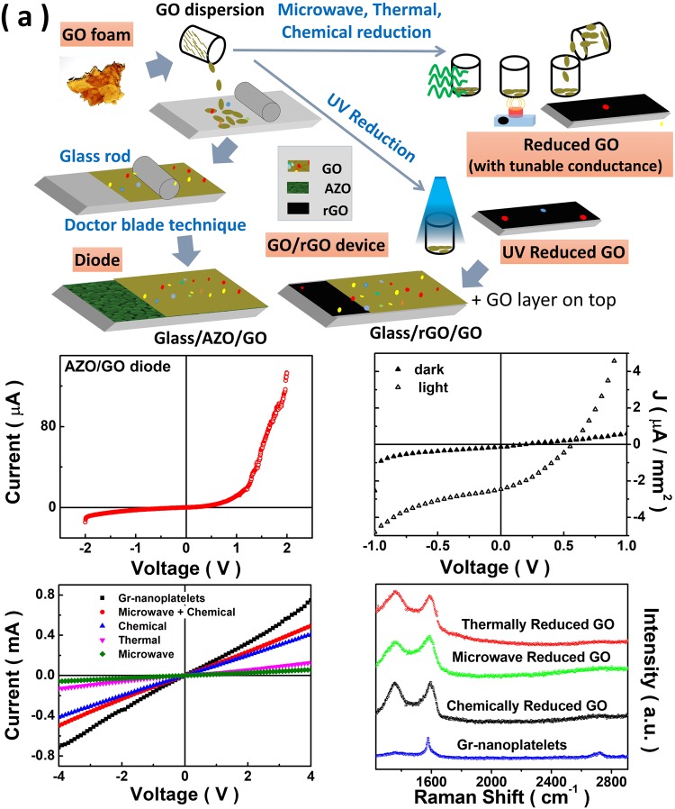
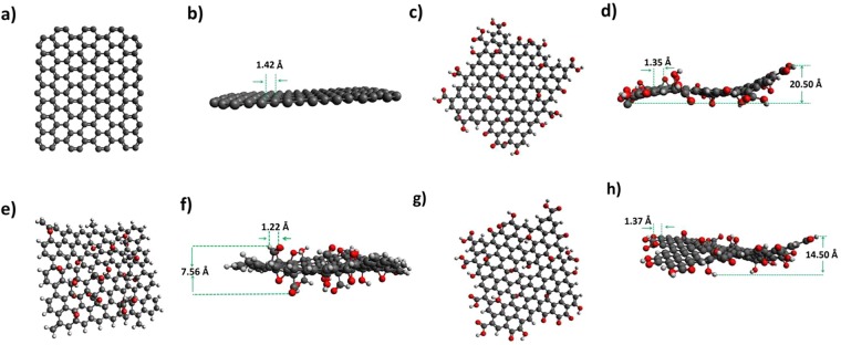
A low cost, non-explosive process for the synthesis of graphene oxide (GO) is demonstrated. Using suitable choice of reaction parameters including temperature and time, this recipe does not require expensive membranes for filtration of carbonaceous and metallic residues. A pre-cooling protocol is introduced to control the explosive nature of the highly exothermic reactions during the oxidation process. This alleviates the requirement for expensive membranes and completely eliminates the explosive nature of intermediate reaction steps when compared to existing methods. High quality of the synthesized GO is corroborated using a host of characterization techniques including X-ray diffraction, optical spectroscopy, X-ray photoemission spectroscopy and current-voltage characteristics. Simple reduction protocol using ultra-violet light is demonstrated for potential application in the area of photovoltaics. Using different reduction protocols together with the proposed inexpensive method, reduced GO samples with tunable conductance over a wide range of values is demonstrated. Density functional theory is employed to understand the structure of GO. We anticipate that this scalable approach will catalyze large scale applications of GO.
Conflict of interest statement
The authors declare no competing interests.
Figures


Similar articles
-
New Insights into the Microstructural Analysis of Graphene Oxide.Curr Org Synth. 2021;18(4):388-398. doi: 10.2174/1570179418666210113162124. Curr Org Synth. 2021. PMID: 33441076
-
Nitrogen-Doped Reduced Graphene Oxide Prepared by Simultaneous Thermal Reduction and Nitrogen Doping of Graphene Oxide in Air and Its Application as an Electrocatalyst.ACS Appl Mater Interfaces. 2015 Dec 9;7(48):26952-8. doi: 10.1021/acsami.5b07757. Epub 2015 Nov 25. ACS Appl Mater Interfaces. 2015. PMID: 26580573
-
Biosynthesis of reduced graphene oxide and its in-vitro cytotoxicity against cervical cancer (HeLa) cell lines.Mater Sci Eng C Mater Biol Appl. 2017 Sep 1;78:198-202. doi: 10.1016/j.msec.2017.04.031. Epub 2017 Apr 7. Mater Sci Eng C Mater Biol Appl. 2017. PMID: 28575975
-
Fabrication Techniques for Graphene Oxide-Based Molecular Separation Membranes: Towards Industrial Application.Nanomaterials (Basel). 2021 Mar 17;11(3):757. doi: 10.3390/nano11030757. Nanomaterials (Basel). 2021. PMID: 33803016 Free PMC article. Review.
-
Graphene Oxide Based Metallic Nanoparticles and their Some Biological and Environmental Application.Curr Drug Metab. 2017;18(11):1020-1029. doi: 10.2174/1389200218666171016100507. Curr Drug Metab. 2017. PMID: 29034831 Review.
Cited by
-
From 2-D to 0-D Boron Nitride Materials, The Next Challenge.Materials (Basel). 2019 Nov 26;12(23):3905. doi: 10.3390/ma12233905. Materials (Basel). 2019. PMID: 31779207 Free PMC article. Review.
-
Measurements of the Electrical Conductivity of Monolayer Graphene Flakes Using Conductive Atomic Force Microscopy.Nanomaterials (Basel). 2021 Sep 30;11(10):2575. doi: 10.3390/nano11102575. Nanomaterials (Basel). 2021. PMID: 34685022 Free PMC article.
-
GO-SWCNT Buckypapers as an Enhanced Technology for Water Decontamination from Lead.Molecules. 2022 Jun 23;27(13):4044. doi: 10.3390/molecules27134044. Molecules. 2022. PMID: 35807300 Free PMC article.
-
2D Materials for Potable Water Application: Basic Nanoarchitectonics and Recent Progresses.Small. 2024 Dec;20(51):e2407160. doi: 10.1002/smll.202407160. Epub 2024 Oct 10. Small. 2024. PMID: 39390843 Free PMC article. Review.
-
Acid-less direct gram scale exfoliation of graphite to partially oxidized graphene.Sci Rep. 2025 Aug 26;15(1):31505. doi: 10.1038/s41598-025-99502-x. Sci Rep. 2025. PMID: 40858911 Free PMC article.
References
-
- Akhavan O, Ghaderi E. Escherichia coli bacteria reduce graphene oxide to bactericidal graphene in a self-limiting manner. Carbon. 2012;50:1853–1860. doi: 10.1016/j.carbon.2011.12.035. - DOI
LinkOut - more resources
Full Text Sources
Other Literature Sources
