. 2018 Jul 9:9:1951-1963.
doi: 10.3762/bjnano.9.186. eCollection 2018.

Defect formation in multiwalled carbon nanotubes under low-energy He and Ne ion irradiation

Affiliations

Defect formation in multiwalled carbon nanotubes under low-energy He and Ne ion irradiation

Santhana Eswara et al. Beilstein J Nanotechnol. .

Abstract

The mechanical, structural, electronic and magnetic properties of carbon nanotubes can be modified by electron or ion irradiation. In this work we used 25 keV He+ and Ne+ ion irradiation to study the influence of fluence and sample thickness on the irradiation-induced damage of multiwalled carbon nanotubes (MWCNTs). The irradiated areas have been characterised by correlative Raman spectroscopy and TEM imaging. In order to preclude the Raman contribution coming from the amorphous carbon support of typical TEM grids, a new methodology involving Raman inactive Au TEM grids was developed. The experimental results have been compared to SDTRIMSP simulations. Due to the small thickness of the MWCNTs, sputtering has been observed for the top and bottom side of the samples. Depending on thickness and ion species, the sputter yield is significantly higher for the bottom than the top side. For He+ and Ne+ irradiation, damage formation evolves differently, with a change in the trend of the ratio of D to G peak in the Raman spectra being observed for He+ but not for Ne+. This can be attributed to differences in stopping power and sputter behaviour.

Keywords: Raman; carbon nanotubes; helium ion microscope; ion irradiation; simulations.


Figures

Figure 1
Figure 1
Raman spectra of multiwalled carbon nanotubes after irradiation with different fluences of a) 25 keV He+, and b) 25 keV Ne+ ions. A laser with a wavelength of 532 nm was used. All the spectra (except the one pointed out) were obtained on suspended free-standing MWCNTs.
Figure 2
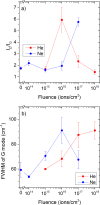
Figure 2
a) Ratio of intensities of D to G band as a function of fluence for 25 keV He and Ne irradiation, and b) full width at half maximum of the G band peak as a function of fluence for 25 keV He and Ne irradiation.
Figure 3
Figure 3
TEM images and Raman spectra after: (A–C) 25 keV He+ irradiation with a fluence of 1018 ions/cm2 (D–F) 25 keV Ne+ irradiation with a fluence of 1017 ions/cm2. While the thinner areas in both cases (A, D) appear to be relatively less damaged due to ion irradiation, the thicker sample areas (B, E) display diffuse contrast characteristic of partial amorphization, with most damage evident for the Ne+ irradiation. The arrows in (D) point to larger structures formed after ion irradiation. Plausible explanations are either by unzipping or other mechanisms of damage formation of MWCNT due to Ne+ irradiation. The structural features observed in these TEM images correlate very well with corresponding Raman spectra (C, F). In the deconvoluted spectra, Lorentz functions in cyan denote the D, G and D’ peaks while the Gaussian contributions from highly disordered areas are coloured in red.
Figure 4
Figure 4
Nuclear and electronic energy loss as a function of sample thickness for a) He+ and b) Ne+ irradiation of suspended carbon.
Figure 5
Figure 5
Sputter yield a) at the top, and b) at the bottom of the sample as a function of fluence for Ne irradiation of carbon samples of different thicknesses of 10–200 nm.
Figure 6
Figure 6
Backscatter yield as a function of gold thickness for He and Ne irradiation of a 30 nm carbon film deposited onto a gold grid. Results have been obtained by SDTRIMSP.
Figure 7
Figure 7
Displacements into the carbon layer normalised to incident ion as a function of gold thickness for He and Ne irradiation of a 30 nm carbon film deposited onto a gold grid. Results were obtained by SDTRIMSP.
Figure 8
Figure 8
Schematic illustration of the sample configuration and the sequence of techniques used in this investigation: a) deposition of MWCNTs in a perforated Au TEM grid, b) irradiation with He+ or Ne+ ions with a fluence of 1014–1018 ions/cm2, c) Raman spectroscopy in the irradiated area with a 532 nm laser, and d) TEM analyses in the irradiated area.

References

    1. Lehman J H, Terrones M, Mansfield E, Hurst K E, Meunier V. Carbon. 2011;49:2581–2602. doi: 10.1016/j.carbon.2011.03.028. - DOI
    1. Krasheninnikov A V, Banhart F. Nat Mater. 2007;6:723–733. doi: 10.1038/nmat1996. - DOI - PubMed
    1. Sammalkorpi M, Krasheninnikov A, Kuronen A, Nordlund K, Kaski K. Phys Rev B. 2004;70:245416. doi: 10.1103/PhysRevB.70.245416. - DOI
    1. Huhtala M, Krasheninnikov A V, Aittoniemi J, Stuart S J, Nordlund K, Kaski K. Phys Rev B. 2004;70:45404. doi: 10.1103/PhysRevB.70.045404. - DOI
    1. Kis A, Csányi G, Salvetat J-P, Lee T-N, Couteau E, Kulik A J, Benoit W, Brugger J, Forró L. Nat Mater. 2004;3:153–157. doi: 10.1038/nmat1076. - DOI - PubMed

LinkOut - more resources