

Note on the use of different approaches to determine the pore sizes of tissue engineering scaffolds: what do we measure?
- PMID: 30119672
- PMCID: PMC6098612
- DOI: 10.1186/s12938-018-0543-z
Note on the use of different approaches to determine the pore sizes of tissue engineering scaffolds: what do we measure?
Abstract
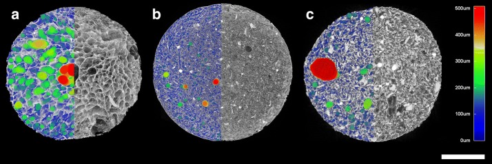
Background: Collagen-based scaffolds provide a promising option for the treatment of bone defects. One of the key parameters of such scaffolds consists of porosity, including pore size. However, to date, no agreement has been found with respect to the methodology for pore size evaluation. Since the determination of the exact pore size value is not possible, the comparison of the various methods applied is complicated. Hence, this study focuses on the comparison of two widely-used methods for the characterization of porosity-scanning electron microscopy (SEM) and micro-computed tomography (micro-CT).
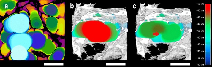
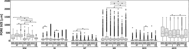
Methods: 7 types of collagen-based composite scaffold models were prepared by means of lyophilization and collagen cross-linking. Micro-CT analysis was performed in 3D and in 2D (pore size parameters were: major diameter, mean thickness, biggest inner circle diameter and area-equivalent circle diameter). Afterwards, pore sizes were analyzed in the same specimens by an image analysis of SEM microphotographs. The results were statistically evaluated. The comparison of the various approaches to the evaluation of pore size was based on coefficients of variance and the semi-quantitative assessment of selected qualities (e.g. the potential for direct 3D analysis, whole specimen analysis, non-destructivity).
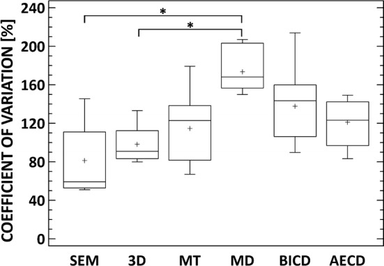
Results: The pore size values differed significantly with respect to the parameters applied. Median values of pore size values were ranging from 20 to 490 µm. The SEM values were approximately 3 times higher than micro-CT 3D values for each specimen. The Mean thickness was the most advantageous micro-CT 2D approach. Coefficient of variance revealed no differences among pore size parameters (except major diameter). The semi-quantitative comparison approach presented pore size parameters in descending order with regard to the advantages thereof as follows: (1) micro-CT 3D, (2) mean thickness and SEM, (3) biggest inner circle diameter, major diameter and area equivalent circle diameter.
Conclusion: The results indicated that micro-CT 3D evaluation provides the most beneficial overall approach. Micro-CT 2D analysis (mean thickness) is advantageous in terms of its time efficacy. SEM is still considered as gold standard for its widespread use and high resolution. However, exact comparison of pore size analysis in scaffold materials remains a challenge.
Keywords: Bone regeneration; Micro-CT; Pore size; Porosity; SEM; Scaffold.
Figures


References
-
- Billström GH. Application of scaffolds for bone regeneration strategies: current trends and future directions. Injury. 2013 - PubMed
-
- Giannoudis PV, Einhorn TA, Marsh D. Fracture healing: the diamond concept. Injury. 2005;38(Suppl 4):S3–S6. - PubMed
-
- Sultana N, Hassan MI, Lim MM. Composite synthetic scaffolds for tissue engineering and regenerative medicine. Cham: Springer International Publishing; 2015.
MeSH terms
Substances
Grants and funding
- "Technological development of post-doc programmes" project/Research and Development for Innovations Operational Programme (RDIOP) co-financed by the European regional development fund and the state budget of the Czech Republic
- registration number CZ.1.05/41.00/16.0346/Research and Development for Innovations Operational Programme (RDIOP) co-financed by the European regional development fund and the state budget of the Czech Republic
- Progres Q29/LF1/Ministerstvo Školství, Mládeže a Tělovýchovy
- 15-25813A/Ministerstvo Zdravotnictví Ceské Republiky
- 14-37368G/Grantová Agentura České Republiky
LinkOut - more resources
Full Text Sources
Other Literature Sources
Molecular Biology Databases
