

A Contactless Sensor for Pacemaker Pulse Detection: Design Hints and Performance Assessment
- PMID: 30126178
- PMCID: PMC6111969
- DOI: 10.3390/s18082715
A Contactless Sensor for Pacemaker Pulse Detection: Design Hints and Performance Assessment
Abstract
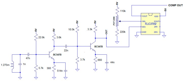
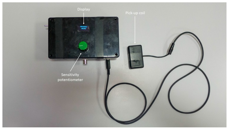
Continuous monitoring of pacemaker activity can provide valuable information to improve patients' follow-up. Concise information is stored in some types of pacemakers, whereas ECG can provide more detailed information, but requires electrodes and cannot be used for continuous monitoring. This study highlights the possibility of a continuous monitoring of pacemaker pulses by sensing magnetic field variations due to the current pulses. This can be achieved by means of a sensor coil positioned near the patient's thorax without any need for physical contact. A simplified model of coil response to pacemaker pulses is presented in this paper, along with circuits suitable for pulse detection. In vitro tests were carried out using real pacemakers immersed in saline solution; experimental data were used to assess the accuracy of the model and to evaluate the sensor performance. It was found that the coil signal amplitude decreases with increasing distance from the pacemaker lead wire. The sensor was able to easily perform pacemaker spike detection up to a distance of 12 cm from the pacemaker leads. The stimulation rate can be measured in real time with high accuracy. Since any electromagnetic pulse triggers the same coil response, EMI may corrupt sensor measurements and thus should be discriminated.
Keywords: coil sensor; pacemaker pulse; pacing monitor; personal healthcare device; pervasive patient monitoring.
Conflict of interest statement
The authors declare no conflict of interest.
Figures


Similar articles
-
Low frequency magnetic emissions and resulting induced voltages in a pacemaker by iPod portable music players.Biomed Eng Online. 2008 Feb 1;7:7. doi: 10.1186/1475-925X-7-7. Biomed Eng Online. 2008. PMID: 18241327 Free PMC article.
-
Low delay rate adaptive pacemaker using FPGA embedded piezoelectric sensor.J Med Eng Technol. 2020;44(7):423-430. doi: 10.1080/03091902.2020.1799097. Epub 2020 Sep 4. J Med Eng Technol. 2020. PMID: 32886006
-
A simple, wide bandwidth, biopotential amplifier to record pacemaker pulse waveform.Med Devices (Auckl). 2016 Sep 16;9:325-329. doi: 10.2147/MDER.S97902. eCollection 2016. Med Devices (Auckl). 2016. PMID: 27695369 Free PMC article.
-
Pacemaker trouble shooting and follow up.Indian Heart J. 2011 Jul-Aug;63(4):356-70. Indian Heart J. 2011. PMID: 22497053 Review.
-
Update on cardiac pacemakers: description, complications, indications, and followup.Cardiovasc Clin. 1985;16(1):177-213. Cardiovasc Clin. 1985. PMID: 3915711 Review.
Cited by
-
Comparation of quality of life in Chinese patients undergoing leadless versus conventional pacemaker implantation.Clin Cardiol. 2023 Jan;46(1):49-56. doi: 10.1002/clc.23939. Epub 2022 Nov 2. Clin Cardiol. 2023. PMID: 36321636 Free PMC article.
-
Wearable Device to Monitor Back Movements Using an Inductive Textile Sensor.Sensors (Basel). 2020 Feb 8;20(3):905. doi: 10.3390/s20030905. Sensors (Basel). 2020. PMID: 32046237 Free PMC article.
-
Contactless Electrocatheter Tracing within Human Body via Magnetic Sensing: A Feasibility Study.Sensors (Basel). 2022 May 20;22(10):3880. doi: 10.3390/s22103880. Sensors (Basel). 2022. PMID: 35632288 Free PMC article.
-
A smart approach to EMG envelope extraction and powerful denoising for human-machine interfaces.Sci Rep. 2023 May 12;13(1):7768. doi: 10.1038/s41598-023-33319-4. Sci Rep. 2023. PMID: 37173364 Free PMC article.
-
Effectiveness and Safety in Remote Monitoring of Patients with Pacemakers Five Years after an Implant: The Poniente Study.Int J Environ Res Public Health. 2020 Feb 23;17(4):1431. doi: 10.3390/ijerph17041431. Int J Environ Res Public Health. 2020. PMID: 32102208 Free PMC article.
References
-
- Gregoratos G., Cheitlin M.D., Conill A., Epstein A.E., Fellows C., Freedman R.A., Hlatky M.A., Naccarelli G.V., Saksena S., Schlant R.C., et al. ACC/AHA Guidelines for Implantation of Cardiac Pacemakers and Antiarrhythmia Devices: Executive Summary—A report of the American College of Cardiology/American Heart Association Task Force on Practice Guidelines (Committee on Pacemaker Implantation) Circulation. 1998;97:1325–1335. doi: 10.1161/01.CIR.97.13.1325. - DOI - PubMed
LinkOut - more resources
Full Text Sources
Other Literature Sources
