. 2018 Aug 29;9(1):3515.
doi: 10.1038/s41467-018-05934-7.

Melting conditions in the modern Tibetan crust since the Miocene

Affiliations

Melting conditions in the modern Tibetan crust since the Miocene

Jinyu Chen et al. Nat Commun. .

Erratum in

Abstract

Abundant granitic rocks exposed in ancient mountain belts suggest that crustal melting plays a major role in orogenic processes. However, complex field relations and superposition of multiple tectonic events make it difficult to determine the role of melting in orogenesis. In contrast, geophysical measurements image present-day crustal conditions but cannot discriminate between partial melt and aqueous fluids. Here we connect pressure-temperature paths of Himalayan Miocene crustal rocks to the present-day conditions beneath the Tibetan plateau imaged with geophysical data. We use measurements of electrical conductivity to show that 4-16% water-rich melt is required to explain the crustal conductivity in the north-western Himalaya. In southern Tibet, higher melt fractions >30% reflect a crust that is either fluid-enriched (+1% H2O) or hotter (+100 °C) compared to the Miocene crust. These melt fractions are high enough for the partially molten rocks to be significantly weaker than the solid crust.


Conflict of interest statement

The authors declare no competing interests.

Figures
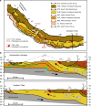
Fig. 1
Fig. 1
Simplified geological map combined with the cross-sections of the northwestern Himalaya and southern Tibet. a The leucogranites used for electrical conductivity measurements (T12-22 in Purang county and DK89 in the base of the Manaslu pluton, red stars on the geological map) were collected in the GHS near the STD. The location of the MT profile probed by Rawat et al. is labeled by the green dashed line. b In the northwestern Himalaya (cross-section A, B), the high electrical conductivity spots of ~0.03 S/m (15–20 km), 0.1–0.2 S/m (20–25 km), and 0.05–0.1 S/m (10–13 km) identified by magnetotelluric data (MT) are labeled P1, P2, and P4, respectively. The green dashed line and circles, respectively, identify the high electrical conductivity layer and spots, as probed by Rawat et al.. c The other spots at ~0.3 S/m (18–20 km) and 0.05–0.1 S/m (10–13 km) are labeled P3 and P5 in the southern Tibet (cross-section C, D). The leucogranites emplaced just beneath the STD have been dated from 26 to 11 Ma, while those emplaced within the THS have been dated from 28 to 7 Ma. ac were adapted from Fig. 1 of Hashim et al.. TS tertiary sediments, LHS Lesser Himalayan Sequence, GHS Greater Himalayan Sequence, THS Tethyan Himalayan Sequence, LS Lhasa terrane, ITS Indus-Tsangpo suture, MFT Main Frontal Thrust, MBT Main Boundary Thrust, MCT Main Central Thrust, STD South Tibet Detachment, GCT Great Counter Thrust, THL Tethyan Himalayan Leucogranite, HHL High Himalayan Leucogranite
Fig. 2
Fig. 2
Half-inch experimental assembly for piston-cylinder adapted to electrical conductivity measurements. It was modified after Sifré et al. and Laumonier et al.. The SEM image shows the inner structure of the assembly after the experiment on the sample T0(11)-0.5
Fig. 3
Fig. 3
Electrical conductivity measurements on dry and hydrous melts plotted in Arrhenius diagrams. The straight lines indicate the fits of the PT–H2O model (Eqs. (1)–(4)). P is the pressure (GPa), w is the water concentration (wt%). a Experimental results for nominally dry samples at different pressures. b Experimental results for different water concentrations at ~1 GPa or ~2 GPa
Fig. 4
Fig. 4
Melting, H2O, temperature, melt fractions, and the multiple solutions explaining the electrical anomalies beneath Tibet. a Relationship between σeff and temperature with different H2O content in the bulk rock at 600 MPa (dashed lines) and 800 MPa (solid lines). The black dashed line refers to the solid rock before melting starts. b, c Range of temperatures (b) or melt fractions (c) and H2O bulk rock contents satisfying the conductivity of 0.03 S/m (P1), 0.1–0.2 S/m (P2), and 0.3 S/m (P3), respectively. The boundaries of fluid-absent and fluid-saturated magmas identified by black straight lines confine the area of possible solutions satisfying the conductivity values previously defined; in between these two boundaries, the regime of fluid-present melting prevails. A single value of conductivity therefore corresponds to a large range of solutions in the T-melt content–H2O content space. All these parameters are, however, related by petrological relationships that can be embodied into a geodynamic scheme such as the G1 PT path (Fig. 5)
Fig. 5
Fig. 5
The electrical conductivity (σeff)–pressure–temperature paths during burial and exhumation of Miocene Himalayan rocks compared with the conductivity of present-day Himalayan crust derived from MT data. a σeff along the PT G1 path (inset diagram) as predicted by the “channel-flow model HT1” and metamorphic petrology; the numbers in Ma on G1 path indicate the particle’s ages to the present. b Electrical conductivity vs. pressure or depth along the G1 path. The red path represents melt in the absence of excess water (i.e., fluid-absent melting, approximately dehydration melting) while the green path illustrates melting in the presence of excess water (i.e., fluid-present melting with excess water content of ca. 1.2%). Dashed curves indicate solid rocks (below solidus), while solid curves (i.e., the lines AB and CD) identify the partially molten domains. Green lines indicate fluid-present melting (AB), while the red lines refers to fluid-absent melting (CD). Arrows represent the direction followed during prograde and retrograde metamorphism along the G1 PT path. The yellow stars and rectangles indicate the conductivity at P1–P3 and P4/P5 (see Fig.1b, c) from the MT studies,, respectively, and their sizes represent 30% uncertainty on the MT results. The percentage values on the curves represent the equilibrium melt fractions along G1, and the blue labels define the melt contents at P1–P3 (see also Table 3). The high conductivity spots (P1 and P2) are consistent with fluid-absent melting while P3 may correspond to fluid-present melting; alternative explanation for P3 are a local melt accumulation process or temperature being 100 °C warmer than those of the G1 PT path (see text)
Fig. 6
Fig. 6
Illustration linking P1–P5 MT anomalies to magmatic processes and crustal-scale transfer of water. The magmatic conditions at the P1–P5 electrical anomalies are given in Table 3. By these magmatic processes, water is transferred from the lower crust (depth >20 km), where partial melting occurs, to the emplacement/crystallization zone of granites (depth = ca. 10–12 km). Aqueous fluids released from solidifying granites may well significantly contribute to the numerous hot springs suggested from their geochemical features. Fluid-absent melting under conditions similar to the G1 PT path can explain the Northwestern Tibet, while beneath the Southern Tibet, either fluid-present melting or a warmer crust is required
Fig. 7
Fig. 7
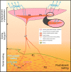
Schematic diagram of granitic magma production, migration, and emplacement in a schematic cross-section of the Himalaya. The inactive shear zones (i.e., STD and MCT) are shown with bold dotted lines, while the active shear zones (i.e., MBT, MFT, and MHT) are shown as bold straight lines. The red regions identify the present-day location of partial melting plus melt ponding (present-day leucogranite plutons) while the blue areas are exhumed and solidified granitic rocks (migmatites and plutons). The numbers illustrate the emplacement of granitic plutons (1) below the STD or (2) above the STD while (3) refers to the top of the partial melting region from where the present-day dykes feeding the growing plutons are nucleating. The fluid identified by Rawat et al. is delineated by the blue droplets, south of the Main Frontal Thrust, and located within the Indian basement. Melting is obviously not occurring in the cold regions of the Indian basement, but this must represent a fluid-enriched zone that is buried beneath the chain. What happens to these fluids is not the kernel of this study but they may well contribute to the process of melting beneath Tibet

References

    1. Brown M. Granite: from genesis to emplacement. Geol. Soc. Am. Bull. 2013;125:1079–1113. doi: 10.1130/B30877.1. - DOI
    1. Patiño Douce AE, Harris N. Experimental constraints on Himalayan anatexis. J. Petrol. 1998;39:689–710. doi: 10.1093/petroj/39.4.689. - DOI
    1. Whittington AG, Hofmeister AM, Nabelek PI. Temperature-dependent thermal diffusivity of the Earth’s crust and implications for magmatism. Nature. 2009;458:319–321. doi: 10.1038/nature07818. - DOI - PubMed
    1. Nábělek PI, Whittington AG, Hofmeister AM. Strain heating as a mechanism for partial melting and ultrahigh temperature metamorphism in convergent orogens: Implications of temperature-dependent thermal diffusivity and rheology. J. Geophys. Res. 2010;115:B12417. doi: 10.1029/2010JB007727. - DOI
    1. Searle M. Crustal melting, ductile flow, and deformation in mountain belts: cause and effect relationships. Lithosphere. 2013;5:547–554. doi: 10.1130/RF.L006.1. - DOI

Publication types