. 2018 Aug 17:12:68.
doi: 10.3389/fnana.2018.00068. eCollection 2018.

New Corticopontine Connections in the Primate Brain: Contralateral Projections From the Arm/Hand Area of the Precentral Motor Region

Affiliations

New Corticopontine Connections in the Primate Brain: Contralateral Projections From the Arm/Hand Area of the Precentral Motor Region

Robert J Morecraft et al. Front Neuroanat. .

Abstract

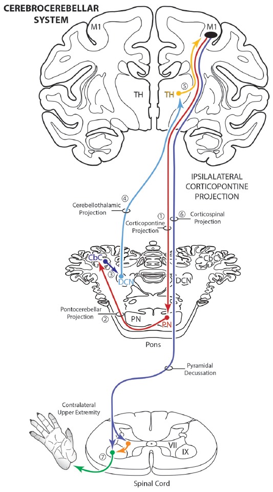
The ipsilateral corticopontine projection (iCPP) represents a massive descending axon system terminating in the pontine nuclei (PN). In the primate, this projection is well known for its dominant influence on contralateral upper limb movements through the classical cerebrocerebellar circuity system. Although a much weaker contralateral corticopontine projection (cCPP) from motor cortex to the paramedian region has been reported in the non-human primate brain, we provide the first comprehensive description of the cCPP from the lateral motor cortex using high resolution anterograde tract tracing in Macaca mulatta. We found a relatively light cCPP from the hand/arm area of the primary motor cortex (M1), comparatively moderate cCPP from ventrolateral premotor cortex (LPMCv) and a more robust and widespread cCPP from the dorsolateral premotor cortex (LPMCd) that involved all nine contralateral PN. The M1 projection primarily targeted the dorsal pontine region, the LPMCv projection targeted the medial pontine region and LPMCd targeted both regions. These results show the first stage of the primate frontomotor cerebrocerebellar projection is bilateral, and may affect both ipsilateral and contralateral limbs. Clinically, the cCPP originating in the non-injured hemisphere may influence the recovery process of the more affected upper extremity following subtotal unilateral damage to the lateral cortical region. The cCPP may also contribute to the mild impairment of the upper limb contralateral to a unilateral cerebellar injury.

Keywords: cerebellum; cerebrocebellar; corticofugal; frontal lobe; hand coordination; pons; pyramidal tract.


Figures

Figure 1
Figure 1
Schematic diagram illustrating the classical cerebrocebellar circuit originating from the primary motor cortex (M1). The sequential stages of the circuit are numbered starting with the powerful descending ipsilateral corticopontine projection (iCPP) to the pontine nuclei (PN) (1). Note that the PN project to the contralateral cerebellar cortex (CbC) (2) and the major cerebellar output from the deep cerebellar nuclei (DCN) ascends to innervate the contralateral thalamus (TH) (4). The thalamus then projects back to the ipsilateral motor cortex (5). The final effect of this cerebrocebellar circuit is on the contralateral upper extremity, via the nearly exclusive contralateral M1 corticospinal projection (CSP) to spinal interneurons (orange) and motoneurons (green) (7). Not illustrated is a small ipsilateral CSP from M1 that represents only 2% of the total terminal bouton CSP with 98% representing the contralateral terminal CSP (Morecraft et al., 2013).
Figure 2
Figure 2
Line drawings of the lateral surface of the cerebral cortex in cases SDM54, SDM57, SDM61 and SDM72 depicting the respective lucifer yellow dextran (LYD), fluorescein dextran (FD) and biotinylated dextran amine (BDA) injection sites into the cortical hand/arm region of M1, caudal part of LPMCd and dorsal part of LPMCv. On the color-coded injection sites, the irregular shaped black line within the injection site represents the boundary between the centrally located injection site core, and peripherally located injection site halo. All injection sites were localized using intracortical microstimulation (ICMS; Morecraft et al., 2007a, 2013).
Figure 3
Figure 3
Photomicrographic montage of representative examples of lateral motor area injection sites and labeled boutons in the contralateral PN taken from immunohistochemically developed tissue sections under brightfield microscopic illumination. (A) Coronal section through the LYD injection site (blue reaction product) placed in the arm representation of M1 in case SDM54. The anatomical orientation (bottom right) of this panel also applies to panel (D). (B) Transverse section through inferior levels of the basis pontis in case SDM54 showing LYD labeled fibers and terminals (black arrowheads) in the contralateral extreme dorsolateral nucleus (ExDL N) following the LYD injection in the M1 arm/hand representation. The inset is a higher power micrograph from the terminal field in the main panel marked by the black asterisk. The anatomical orientation (bottom right) of this panel also applies to panels (C,E,F). The micron bar (bottom left) applies to panels (C,F). (C) Transverse section through lower levels of the pons in case SDM54 showing labeled terminals in the dorsal nucleus (D N) following an injection of LYD into M1 (blue reaction product and black arrow heads) and BDA into LPMCd (brown reaction product and brown arrowheads). The inset is from a different focal plane of the same section showing a BDA labeled fiber (brown) en passant, and LYD labeled terminal boutons (blue). The blue arrows show the pathway direction of labeled fibers passing through the dorsal nucleus en route to the more laterally located dorsal tier nuclei (i.e., to the dorsal lateral nucleus and extreme dorsolateral nucleus). (D) Low power image depicting the FD (blue reaction product) and BDA (brown reaction product) injection sites in LPMCd and LPMCv, respectively in case SDM57. The calibration bar in the bottom left of the panel also applies to panel (A). (E) Transverse section though mid-levels of the pontine gray matter in case SDM57 showing BDA terminal boutons (brown arrowheads) and LYD labeled terminal boutons (black arrowheads) in the contralateral reticular nucleus (Rt N). The inset is from a different focal plane of the same tissue section showing a terminal cluster of LYD labeled axons and terminals. (F) Transverse section through mid-levels of the basis pontis in case SDM57 showing BDA labeled terminals (brown arrowheads) in the contralateral dorsal medial nucleus (DM N). The inset is a higher power micrograph from the terminal field in the main panel marked by the black asterisk. The brown arrows show the dorsolateral trajectory of labeled fibers passing through the dorsomedial nucleus en route to the laterally located dorsal tier nuclei (i.e., dorsal nucleus, dorsal lateral nucleus and extreme dorsolateral nucleus). Abbreviations: cs, central sulcus; d, dorsal; l, lateral; LPMCd, dorsolateral premotor cortex; LPMCv, ventrolateral premotor cortex; m, medial; M1, primary motor cortex; v, ventral. For other abbreviations see Figure 2.
Figure 4
Figure 4
Line drawings of transverse sections depicting the topographical distribution of labeled terminals (black dots) from superior (I) to inferior (IX) levels of the basis pontis in case SDM54 following an injection of LYD into the arm/hand region of M1. Note terminal labeling is primarily located in the dorsal region of the PN and at middle and inferior pontine levels. Each nucleus is identified by the color coded legend in the bottom left of the figure. The descending fibers of the longitudinal pontine fasciculus (LPF) are located in the central region of the peduncular nucleus. Abbreviations: d, dorsal; l, lateral; m, medial; v, ventral.
Figure 5
Figure 5
Line drawings of transverse sections depicting the topographical distribution of labeled terminals (black dots) from superior (I) to inferior (IX) levels of the basis pontis in case SDM57 following an injection of FD into the caudal region of LPMCd. Note terminal labeling is primarily located in the dorsal and medial regions of the basis pontis and is particularly prominent at levels IV through VII. Abbreviations: d, dorsal; l, lateral; m, medial; v, ventral.
Figure 6
Figure 6
Line drawings of transverse sections depicting the topographical distribution of labeled terminals (black dots) from superior (I) to inferior (IX) levels of the basis pontis in case SDM57 following an injection of BDA into the dorsal region of LPMCv. Note terminal labeling is nearly exclusively located in the medial pontine region and at middle and inferior pontine levels. Abbreviations: d, dorsal; l, lateral; m, medial; v, ventral.
Figure 7
Figure 7
Summary diagram illustrating the main pathways taken by labeled axons to innervate the gray matter of the contralateral basis pontis. The thick descending arrow denotes the LPF. One major route emerges from the LPF and courses dorsally through the median nucleus (a,b) to innervate the dorsomedial, reticular, dorsal, dorsolateral and dorsolateral extreme PN. This pathway also contains a contingent of fibers that continue dorsally through the contralateral basis pontis to enter and innervate gray matter targets in the contralateral pontine tegmentum. Injections in the lateral premotor cortex (LPMC) also gave rise to a weaker, ventrally directed pathway (c). Also illustrated is the commonly recognized route taken by fibers from the LPF that innervate the contralateral pontine tegmentum (d). Specifically these fibers emerge from the LPF, enter the ipsilateral tegmentum, then cross the midline within the tegmentum proper. Abbreviations: D, dorsal nucleus; DL, dorsolateral nucleus; DM, dorsomedial nucleus; ExDL, extreme dorsolateral nucleus; L, lateral nucleus; M, median nucleus; PM, paramedian nucleus; PN, peduncular nucleus; Rt, reticular nucleus; V, ventral nucleus.
Figure 8
Figure 8
(A) Bar graphs illustrating the total estimated number of contralateral corticopontine boutons and ipsilateral corticopontine boutons following injections of high resolution tract tracer into M1, LPMCd and LPMCv in each experimental case. (B) Bar graphs illustrating the percent distribution of the contralateral corticopontine boutons and ipsilateral corticopontine boutons following injections of high resolution tract tracer into M1, LPMCd and LPMCv in each experimental case.
Figure 9
Figure 9
Estimated number of contralateral corticopontine boutons within each pontine nucleus for each injection site in M1, LPMCd and LPMCv in each experimental case.
Figure 10
Figure 10
Schematic diagram of the classical motor cerebrocebellar system with the modification of the contralateral corticopontine projection (cCPP) in the first stage (1) of the circuit. Specifically, we found M1, LPMCd and LPMCv (not illustrated) all gave rise to a cCPP (1), demonstrating that the corticopontine projection from the lateral motor region is bilateral. Considering the sequential stages of the cerebrocebellar circuit as classically reported (stages 2–7, and as illustrated in Figure 1), the overall effect of the cCPP would theoretically be on the ipsilateral upper extremity. Thus, the CPP may play a role in both right and left upper limb movements.
Figure 11
Figure 11
Summary diagram illustrating a potential contribution of the cCPP on the subcortical cerebellar circuit influencing the red nucleus which in turn projects to the contralateral spinal cord. The organization of the subcortical circuit positioned downstream on the cCPP is based upon the circuit characteristics of the classic cerebello-rubral (dentato-rubral) projection system.
Figure 12
Figure 12
Summary diagram (A) illustrating the potential influence of the cCPP from the non-lesioned hemisphere on the recovery process of the more affected limb following subtotal unilateral motor cortex injury. Following partial motor cortex destruction, a cCPP may augment the effects of the surviving components of the iCPP (red dashed line) originating from the lesioned hemisphere. Also illustrated (B) is the potential parallel contribution of a cCPP to motor recovery of the more affected limb through the rubrospinal projection, particularly following massive unilateral motor cortex injury. In both illustrations the cross hatching represents lesioned cortex.

References

    1. Afifi A. K., Bergman R. A. (1980). Basic Neuroscience. Baltimore, MD: Urban and Schwarzenberg.
    1. Anens E., Kristensen B., Häger-Ross C. (2010). Reactive grip force control in persons with cerebellar stroke: effects on ipsilateral and contralateral hand. Exp. Brain Res. 203, 21–30. 10.1007/s00221-010-2203-9 - DOI - PubMed
    1. Belhaj-Saïf A., Karrer J. H., Cheney P. D. (1998). Distribution and characteristics of poststimulus effects in proximal and distal forelimb muscles from red nucleus in the monkey. J. Neurophysiol. 79, 1777–1789. 10.1152/jn.1998.79.4.1777 - DOI - PubMed
    1. Bestmann S., Swayne O., Blankenburg F., Ruff C. C., Teo J., Weiskopf N., et al. . (2010). The role of contralesional dorsal premotor cortex after stroke as studied with concurrent TMS-fMRI. J. Neurosci. 30, 11926–11937. 10.1523/JNEUROSCI.5642-09.2010 - DOI - PMC - PubMed
    1. Brodal P. (1978a). The corticopontine projection in the rhesus monkey. Origin and principles of organization. Brain 101, 251–283. 10.1093/brain/101.2.251 - DOI - PubMed

LinkOut - more resources