. 2018 Aug 31;4(8):eaat1659.
doi: 10.1126/sciadv.aat1659. eCollection 2018 Aug.

Acoustophoretic printing

Affiliations

Acoustophoretic printing

Daniele Foresti et al. Sci Adv. .

Abstract

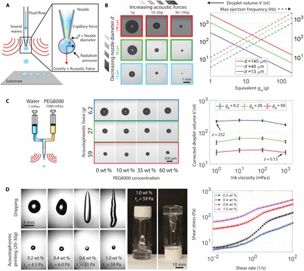
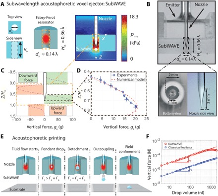
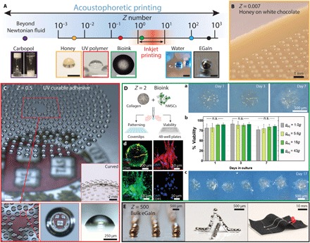
Droplet-based printing methods are widely used in applications ranging from biological microarrays to additive manufacturing. However, common approaches, such as inkjet or electrohydrodynamic printing, are well suited only for materials with low viscosity or specific electromagnetic properties, respectively. While in-air acoustophoretic forces are material-independent, they are typically weak and have yet to be harnessed for printing materials. We introduce an acoustophoretic printing method that enables drop-on-demand patterning of a broad range of soft materials, including Newtonian fluids, whose viscosities span more than four orders of magnitude (0.5 to 25,000 mPa·s) and yield stress fluids (τ0 > 50 Pa). By exploiting the acoustic properties of a subwavelength Fabry-Perot resonator, we have generated an accurate, highly localized acoustophoretic force that can exceed the gravitational force by two orders of magnitude to eject microliter-to-nanoliter volume droplets. The versatility of acoustophoretic printing is demonstrated by patterning food, optical resins, liquid metals, and cell-laden biological matrices in desired motifs.


Figures

Fig. 1
Fig. 1. Acoustophoretic printing.
(A) Schematic view of acoustophoretic printing, in which the radiation pressure provides an additional force that aids drop formation and ejection. (B) Optical images of droplets formed as a function of varying acoustophoretic forces and nozzle diameter d (left), images obtained under simple dripping mode (Fg), and log-log plot of droplet volume and maximum ejection frequency over the range of acoustophoretic forces explored (right). (C) Schematic view of a two-component nozzle that delivers a mixture of water and PEG (molecular weight = 8000 g/mol) ranging from 0 to 60 wt % PEG (viscosity between 1 and 1000 mPa·s, respectively) (left), optical images of droplets generated during acoustophoretic printing of these model fluids (middle), and log-log plot of droplet volume as a function of ink viscosity (right, black bars denote 1 pixel = 9 μm). (D) Acoustophoretic printing of prototypical yield stress fluids composed of 0.2 to 1.0 wt % carbopol in water alongside images of an ink vial containing a carbopol solution of 1.0 wt % (left, middle) and log-log plot of shear stress as a function of shear rate for these solutions.
Fig. 2
Fig. 2. Principle and acoustophoretic properties of the subWAVE.
(A) Schematic view of the subwavelength acoustophoretic voxel ejector (left). The resonance (schematically shown in red) leads to high acoustic pressure amplification while keeping the field strongly confined (right). (B) Side view of the experimental setup (top) and close-up of the tapered nozzle (λ ≈ 14 mm) (bottom). Calculated vertical force distribution inside the subWAVE (C) and its experimental validation (D). (E) Schematic illustration of acoustophoretic printing, which shows that when the total acoustophoretic and gravitational forces exceed the capillary force, droplet detachment and outcoupling from the subWAVE enable patterning on any substrate. (F) Log-log plot of vertical force generated within the subWAVE as a function of drop volume compared to a classical standing-wave levitator.
Fig. 3
Fig. 3. Drop-on-demand acoustophoretic printing.
(A) Drop-on-demand printing of a rasterized (large-area) image, in which fluid dispensing is synchronized with the substrate movement to provide spatial control over the patterned droplets. (B) Schematic view of droplet deposition (top) illustrating the exit angle α, drop trajectory Δ, distance L between the nozzle and substrate, and offset distance between subWAVE exit and substrate. Images of patterned droplet traces as a function of acoustophoretic pressure ga. Scale bar, 2 mm. (C) Plot of positional accuracy of droplets deposited via acoustophoretic printing as a function of this offset distance L. The subWAVE can be placed as close as 1 mm (0.07λ) from the substrate without hindering the drop deposition process. (Note that the drop trajectory and exit angle are plotted as SDs.)
Fig. 4
Fig. 4. Acoustophoretic printing of food, optical, biological, and electrically conductive materials.
(A) Schematic illustration of the broad Z range enabled by acoustophoretic printing, which extends over nearly six orders of magnitude, and corresponding images of droplets patterned by this approach. Note that the typical Z range for inkjet printing is highlighted in red. Scale bars, 500 μm. (B) Honey droplets printed on white chocolate. (C) Optical adhesive resin printed in a spiral motif yielding a microlens array. (D) Acoustophoretic printing of hMSC-laden collagen I ink for viability testing and patterning. (a) Bright-field images of printed droplets composed of hMSCs in a collagen I matrix (geq = 43g) cultured for 7 days. (b) Cell viability of acoustophoretically printed droplets with increasing acoustic force (n = 6). n.s., not significant. (c) Bright-field image of patterned droplets at day 17 (geq = 18g). (d) Representative confocal microscopy images of an immunofluorescently stained, printed droplet (geq = 43g) cultured to day 17 and a higher-magnification region stained for CD105 (green), CD90 (red), CD45 (gray), and nuclei [4′,6-diamidino-2-phenylindole (DAPI), blue]. (E) Acoustophoretic printing of a liquid metal ink composed of eGaIn patterned as individual droplets at room temperature in noncontact mode.

References

    1. Truby R. L., Lewis J. A., Printing soft matter in three dimensions. Nature 540, 371–378 (2016). - PubMed
    1. Derby B., Inkjet printing of functional and structural materials: Fluid property requirements, feature stability, and resolution. Annu. Rev. Mater. Res. 40, 395–414 (2010).
    1. Gruene M., Unger C., Koch L., Deiwick A., Chichkov B., Dispensing pico to nanolitre of a natural hydrogel by laser-assisted bioprinting. Biomed. Eng. Online 10, 19 (2011). - PMC - PubMed
    1. Zhang Z., Xiong R., Mei R., Huang Y., Chrisey D. B., Time-resolved imaging study of jetting dynamics during laser printing of viscoelastic alginate solutions. Langmuir 31, 6447–6456 (2015). - PubMed
    1. H. Yang, Y. He, C. Tuck, R. Wildman, R. Hague, High viscosity jetting system for 3D reactive inkjet printing, in Twenty Forth Annual International Solid Freeform Fabrication Symposium—An Additive Manufacturing Conference, Austin, TX, 12 to 14 August 2013, pp. 505–513.

Publication types